3. INSTALLATION
3.2.1 Installing the Certied Junction Box
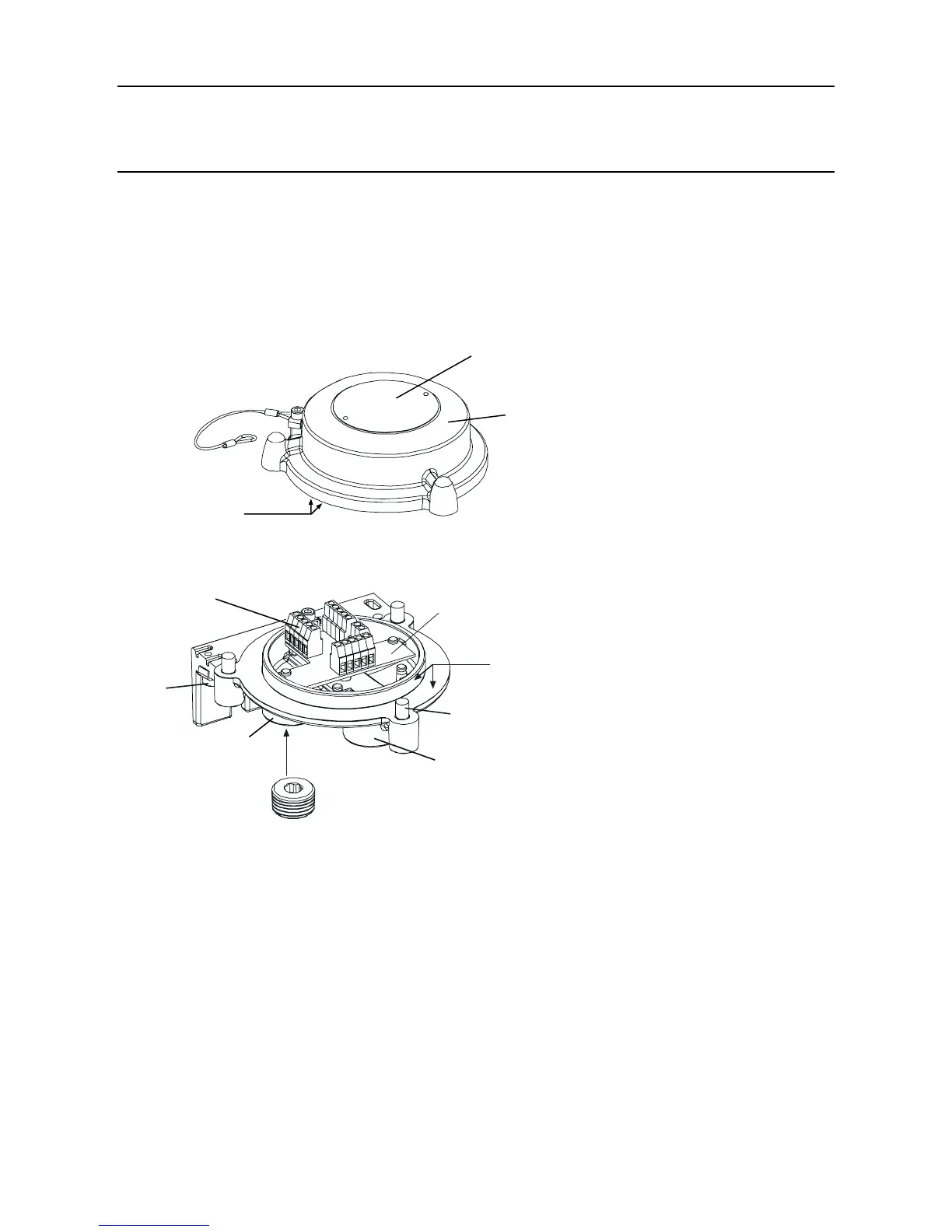
Caution: EnsurethattheCertiedJunctionBoxamepathisnotdamagedduringthis
procedure.TheamepathisformedbythematingsurfacesoftheCertied
JunctionBoxtopandbase(seediagrams).
(1) Isolate all associated power supplies and ensure that they remain OFF during the installation
procedure. Ensure a gas free atmosphere.
(2) AttachtheCertiedJunctionBoxtothesupportingstructure.
Drill two mounting holes (68mm apart) and use the unit’s mounting slots in the base with
either two M10 bolts or a single 10mm U-bolt.
(3) RemovetheCertiedJunctionBoxlid.
Unscrew the three captive M8 bolts. The lid is retained by a metal retaining cable attached to
the base.

 Loading...


