3. INSTALLATION
(3) Detach the top of the Transmitter Unit.
Unscrew the three captive M8 bolts underneath the base. Lift the top clear of the locating
pins. Take care not to damage or strain the ribbon cable connecting the top and the base.
Support the top and ensure that it is supported whilst the next step is carried out.
(4) UnlatchtheribboncableZeroInsertionForce(ZIF)connectorontheInterconnectPCB.
Grip the ends of the ZIF and pull it vertically upwards until it is felt to stop and the ribbon cable
is loose.
(5) Pull the ribbon cable clear.
Remove the top and take to a workshop area.
3.3.2 Removing the Main PCB assembly from the top
(1) Placethetopwiththecerticatefacedownonaatsurface.
This provides access to the components inside the top.
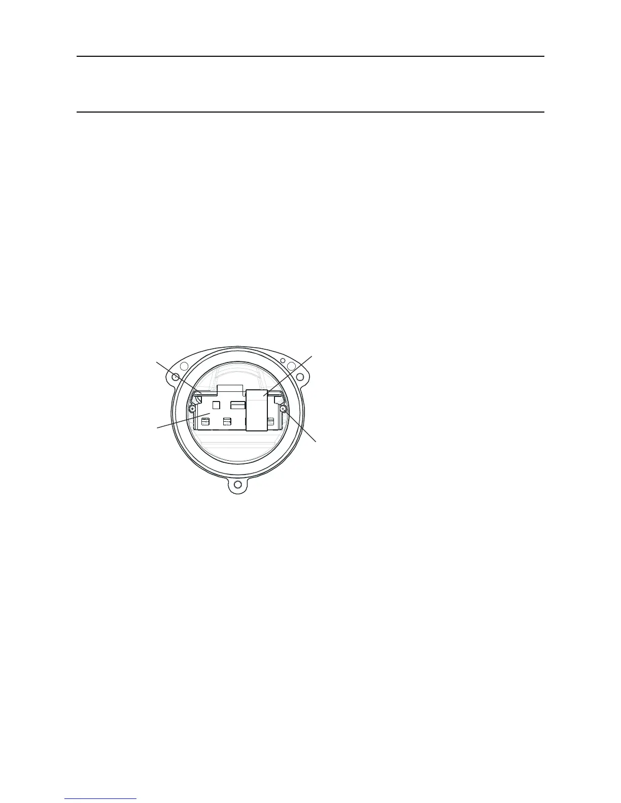
Ribbon
cable
PCB
baffle
PCB
baffle
PCB baffle
securing screw
(2 off)
Main PCB
assembly
(2) RemovethePCBBafefromtheTransmitterUnittop.
UnscrewandremovethetwoPCBBafesecuringscrews.
(3) DisconnecttheyingleadplugandsocketconnectingtheMainPCBPottedassemblyto
the top.
(4) Slide the Main PCB Potted assembly out of the Apex Transmitter Unit top.

 Loading...


