Note: Theboardissuppliedwiththemountingpillarsttedtoit.
Thisproceduredescribeshowto:
• remove the Transmitter Unit top
• remove the Main PCB assembly from the top
• t the LonWorks Communication Board to the Main PCB
• ret the Main PCB assembly into the top
• connect the LonWorks network wiring
• ret the Transmitter Unit top
• operational check and binding the LonWorks Communication Board to
the network
Refer to the General Installation Guidelines at the beginning of this chapter.
3.3.1 Removing the Transmitter Unit top
Cautions:
1. Observe precautions for handling electrostatic discharge sensitive devices.
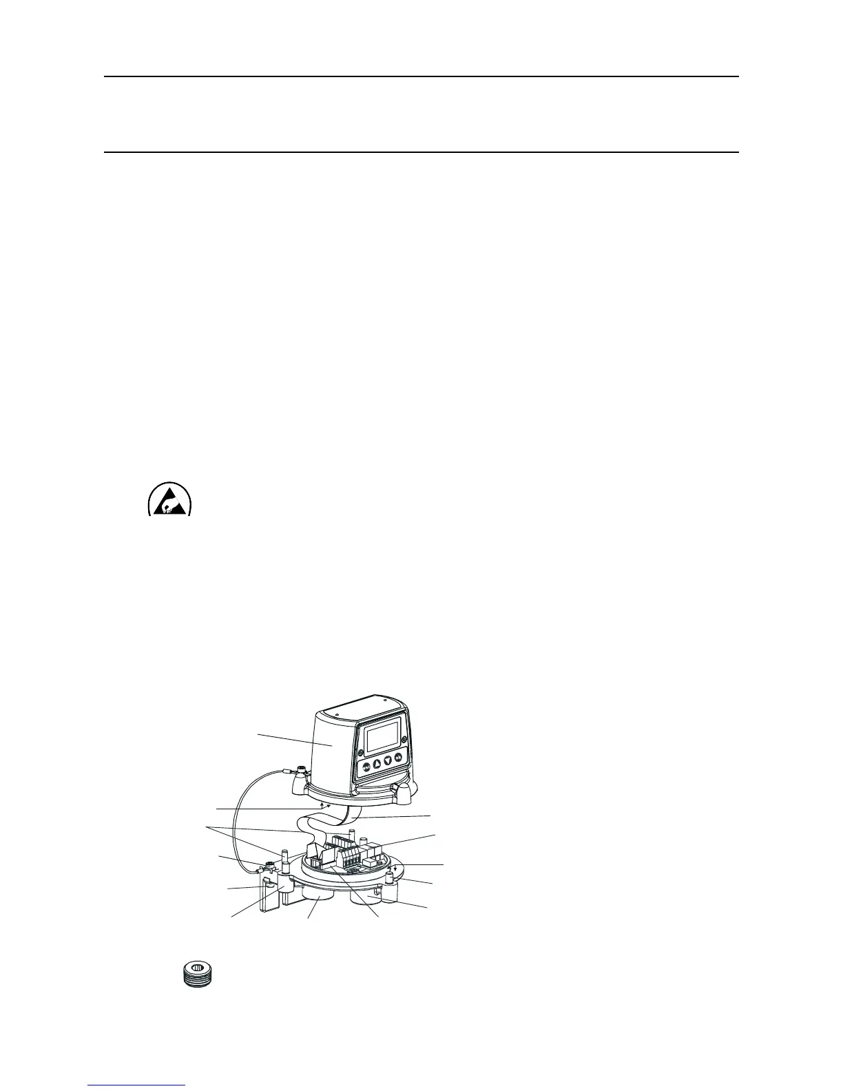
2. EnsurethattheApexTransmitterUnitamepathisnotdamagedduringthisprocedure.
TheamepathisformedbythematingsurfacesoftheApexTransmitterUnittopand
base (see diagram).
(1) Isolate all associated power supplies and ensure that they remain OFF during this procedure.
Ensure a gas free atmosphere.
(2) DisconnectfromtheTransmitterUnitbasethewireretainingcablettedbetweenthetopand
the base.
Unscrew and remove the single M6 hexagon screw that secures the cable to the base.
3. INSTALLATION

 Loading...


