3. INSTALLATION
(4) Fitandconnecttheeldwiring.
See the subsequent tables and diagram for wiring details. Use either:
Conduit - using one or both of the ¾NPTconduitentries.Ensurethataconduitsealingtting
is installed within 18" of the enclosure on all conduit runs.
Cable-usinganysuitableameproofcableentrydevicecertiedasEquipmenttoDirective
94/9/EC(ATEX).
Notes:
1. Allunusedcable/conduitentriesmustbesealedwithacertiedsealingplug(oneplugis
suppliedtted).
2. For a multi-sensor system using a network loop, both cable/conduit entries are used, one
bringingtheloopconnectionsinandtheothertakingthemoutofthebox.Removethetted
certiedsealingplugfromthesparecable/conduitentry.
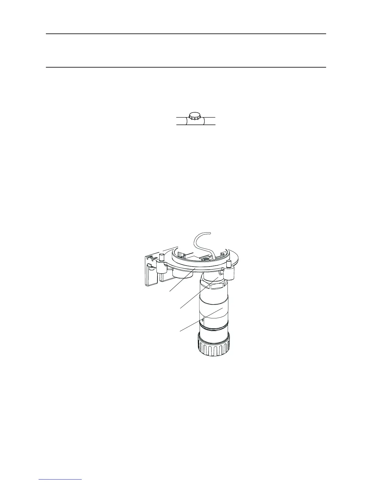
3.2.2 Fitting the Certied Sensor
(1) FittheCertiedSensortotheCertiedJunctionBox.
Certified Sensor
mounting point
Certified Sensor
Junction
Box base
Pass the sensor connecting cable through the sensor mounting point and then screw the
sensorrmlyintothesensormountingpointuntilitisfullyhome.
(2) Connect the sensor wiring.
See the following diagram and table for wiring details.

 Loading...


