3. INSTALLATION
SetthelinkontheInterconnectPCBfortherequiredControllerAreanetwork(CAN)setting.
See 3.2.4.
(4) RetthetoptotheCertiedJunctionBoxbase.
Cautions:
1. EnsurethatthereisnomoistureinsidetheCertiedJunctionBoxbeforettingthelid.
2. Use only the captive bolts supplied, replacement with alternative bolts will invalidate
certication.
ThetopshouldbelocatedusingthelocatingpinsontheCertiedJunctionBoxbaseandthen
lowered onto the base. Ensure that the lid retaining cable and/or wiring are not trapped and
the O-ring in the top is correctly located. Check that there is no discernible gap between the
top and the base. Tighten the captive M8 bolts to 5Nm (3.68 foot-pounds).
3.2.3 Installing the Gas Sensing Cartridge
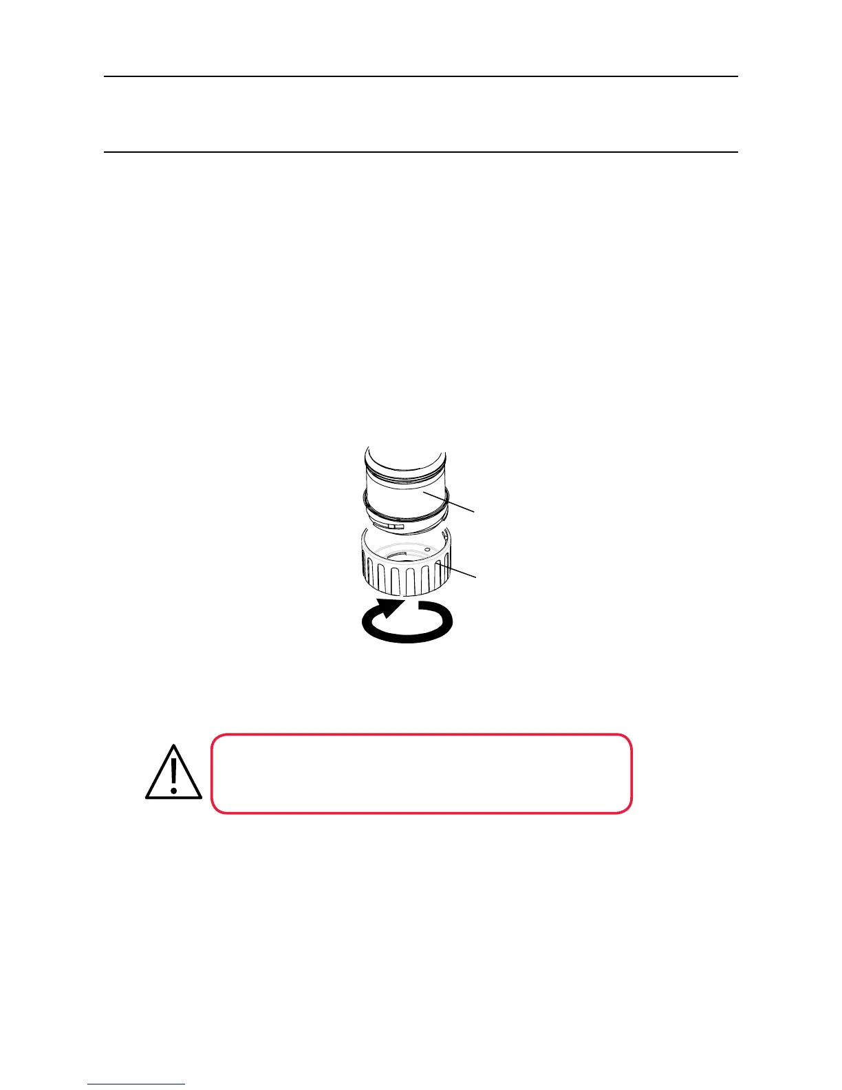
(1) RemovethecapfromtheCertiedSensorbody.
Rotate the cap or accessory 1/4 turn in an anticlockwise direction to release the
bayonettting.
(2) Fit the gas sensing cartridge into the sensor body.
WARNING
Sensor Cartridges may contain corrosive solutions.
Dispose of according to local and national regulations.
Eachcartridgeisprovidedwithacerticateofcalibration(printedonthereverseofthe
instruction sheet, Part No: 2110M8015, supplied with the cartridge) that guarantees that the
cartridgeiscalibratedandreadyforuse.Beforeinstallingacartridgecheckthatthenumber
on the cartridge label matches the gas type and range for the function required.

 Loading...


