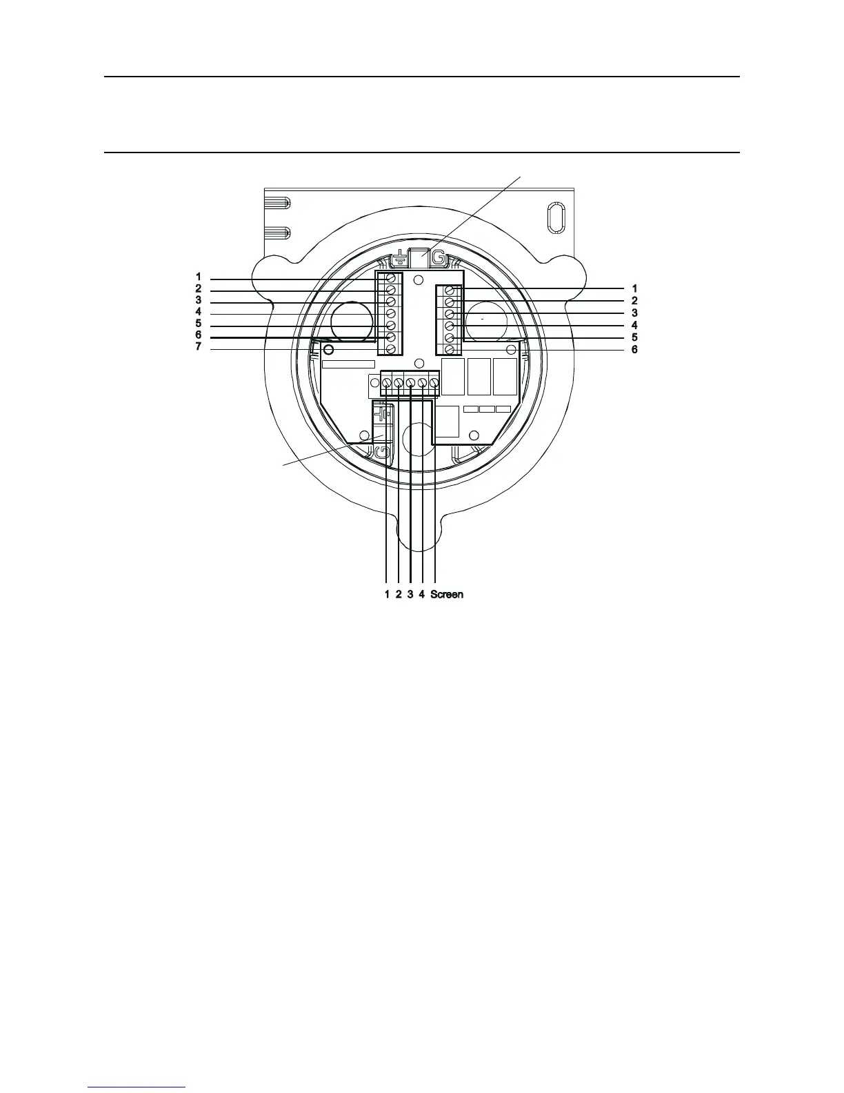
SK3
SK4
SK6
(3) ConguretheTransmitterUnitifrequired.
SetthelinksontheInterconnectPCBfortherequiredrelaycontactsettingsandforthe
4-20mA topology. See 3.1.4.
(4) Retthetoptothebase.
Cautions:
1. Ensurethatthereisnomoistureinsidetheunitbeforettingthetop.
2. Use only the captive bolts supplied, replacement with alternative bolts will invalidate
certication.
Follow the reverse of the removal procedure supporting the top. The top should be positioned
using the locating pins on the Apex Transmitter Unit base and then lowered onto the base.
Ensure that the lid retaining cable and wiring is not trapped and the O-ring in the top is
correctly located.
Ensure that the ribbon cable is not twisted and is correctly positioned. Check that there is
no discernible gap between the top and the base. Tighten the three captive M8 bolts to 5Nm
(3.68 foot-pounds).

 Loading...


