3. INSTALLATION
(4) RetthetoptotheTransmitterUnitbase.
Cautions:
1. Ensurethatthereisnomoistureinsidetheunitbeforettingthetop.
2. Use only the captive bolts supplied, replacement with alternative bolts will invalidate
certication.
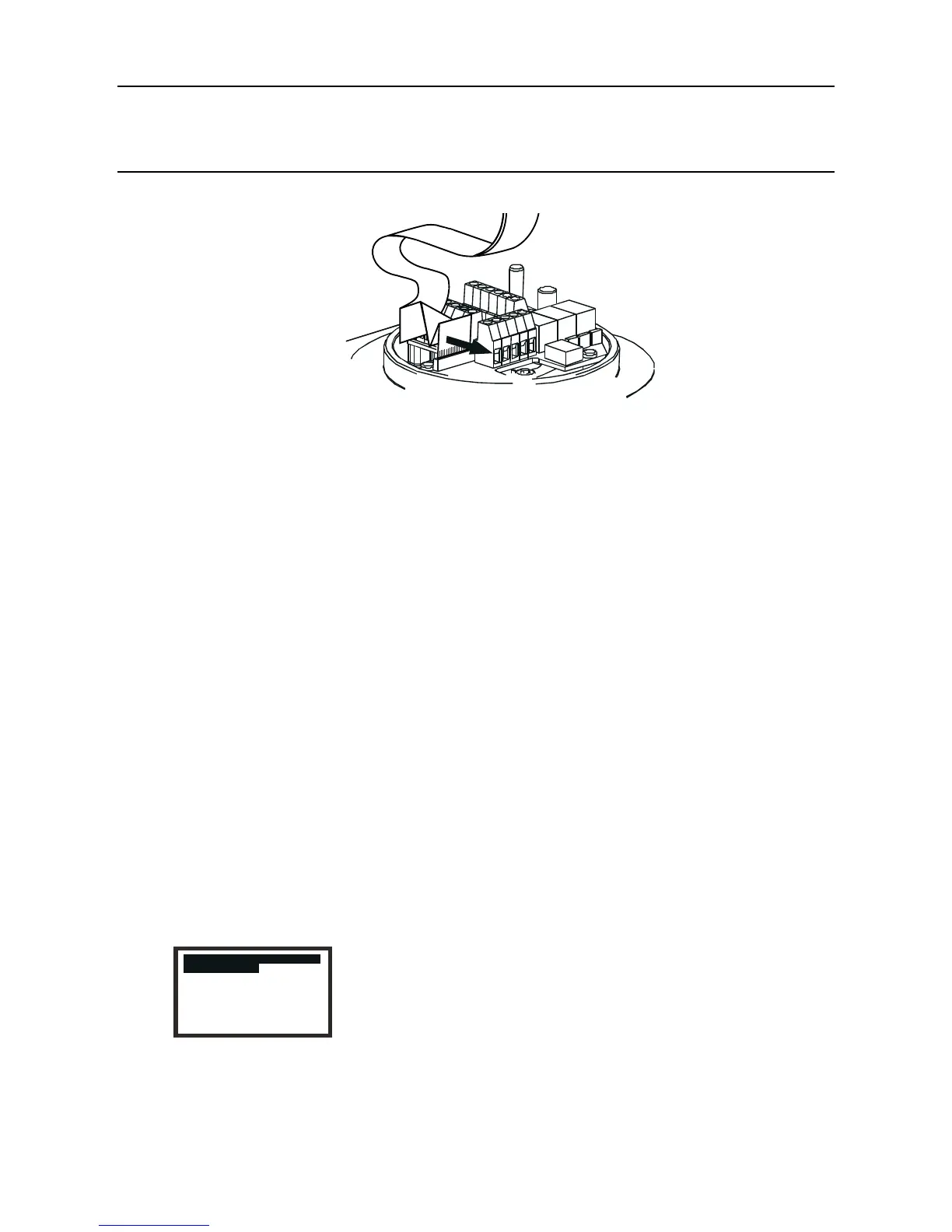
The top should be located using the locating pins on the Apex base and then lowered onto
the base. Ensure no wires are trapped and the O-ring in the top is correctly located.
Check that there is no discernible gap between the top and the base.
Tighten the captive M8 bolts to 5Nm (3.68 foot-pounds).
(5) Check for correct operation of the system by carrying out the procedures described in the
following section.
3.3.7 Operational Check
After installing the Communication Board and connecting the communication network wiring it is
necessarytocheckthattheApexTransmitterUnit,CertiedSensorandCommunicationBoardare
working correctly together and also bind the equipment, which now acts together as a node, to the
communication network.
(1) Power-up the Transmitter Unit.
(2) Check that the Transmitter Unit completes its start-up sequence successfully.
The Gas Reading should be displayed. Refer to the Fault Diagnosis sub-section in
Chapter 4 if an error message is displayed.
(3) Press the esc button on the front panel.
The Main Menu is displayed.
 Loading...


