EasyManua.ls Logo

Honeywell EXCEL 5000 User Manual

Honeywell EXCEL 5000
282 pages
To Next Page IconTo Next Page
To Previous Page IconTo Previous Page
Page #244 background imageLoading...
Page #244 background image
EXAMPLES CARE CONTROL ICONS
74-5577–33 (US) 246
EN2B-0184 GE51 R0518 (Europe)
Attenuator
Purpose In many applications, the desired calculation is not based on a momentary value
such as outdoor air temperature but is averaged over an hour. Instead of an exact
mean value, you can calculate a good approximation by “attenuating” the value. For
example, the following formula approximates outdoor air temperature:
Approx. OAT
new
= INT(MomentaryOAT - Approx.OAT
old
)
INT stands for an integral function.
Control Icons Use the SWI, MAT, and DIF control icons.
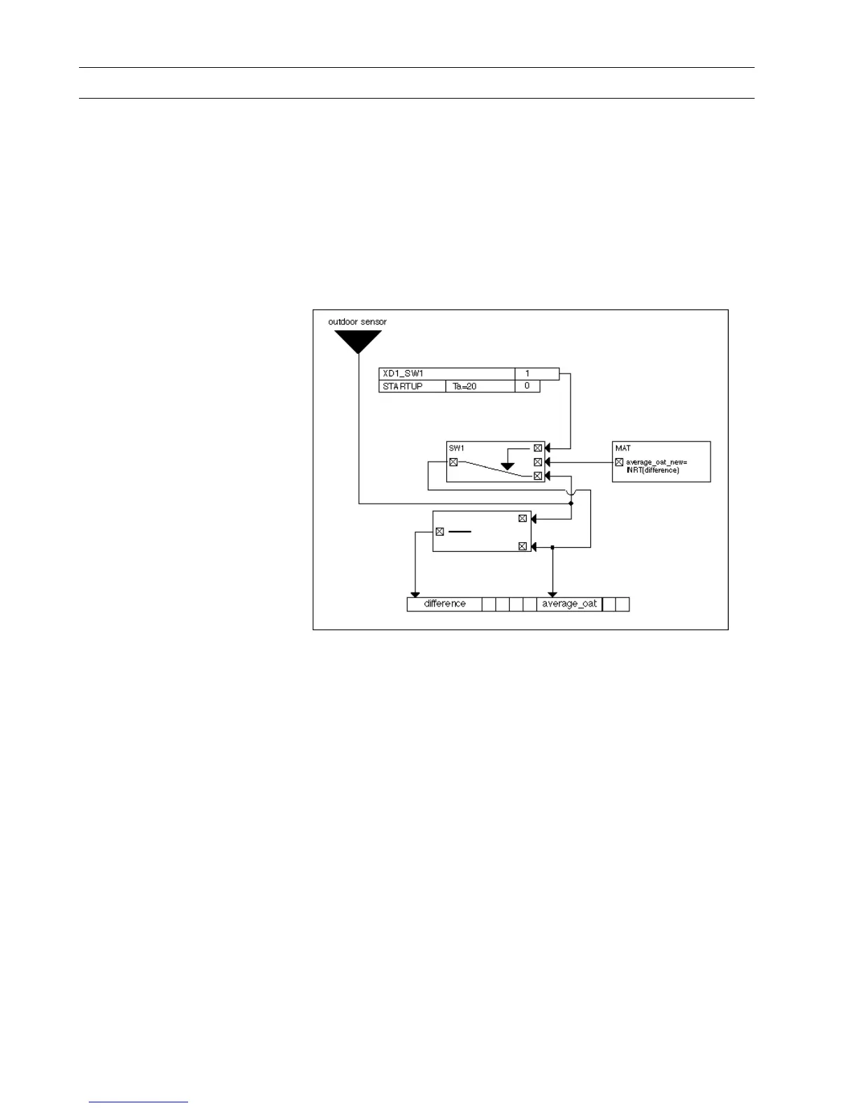
Example The following diagram shows the control loop and switching table setup for this
application.
The closed loop control symbol DIF calculates the differential between the
momentary outdoor temperature and the old approximate outdoor temperature. The
MAT symbol provides a formula to integrate the difference (INT function). The
integral function uses TI (reset time) equal to 60 minutes and has a limit value (LIM)
of 50C (122F).
Note that the “difference” pseudopoint is an analog flag. It does not have to be
available for operator display.
The MAT output calculates the appropriate outdoor temperature. During equipment
start-up, actual outdoor temperature overrides the calculated temperature. For
example, start-up maintains 20 seconds on zero, then follows with an approximation
of the outdoor temperature. Before this, the approximate outdoor temperature
equals the momentary outdoor temperature. This action correctly initializes the
integral function.
To use the STARTUP point, see Appendix B: Startup User Address.

Table of Contents

Other manuals for Honeywell EXCEL 5000

Question and Answer IconNeed help?

Do you have a question about the Honeywell EXCEL 5000 and is the answer not in the manual?

Honeywell EXCEL 5000 Specifications

General IconGeneral
BrandHoneywell
ModelEXCEL 5000
CategoryControl Systems
LanguageEnglish

Summary

Introduction to Control Icons

Control Icon Operation

Explains how control icons function, including internal parameters and I/O dialog boxes.

Control Icon Table

Provides a list of control icons with their names, symbols, and brief descriptions.

Alphabetic Reference of Control Icons

Absolute (Excel Web / Excel Web II) Icon

Describes the Absolute control icon, its function, and I/O.

Addition / ADD Icon

Details the Addition/ADD control icon for summing input values.

ADH2 (Excel Web / Excel Web II) Icon

Explains the ADH2 control icon for legacy RACL heating curve slope calculation.

Analog Switch / SWI Icon

Describes the Analog Switch/SWI icon for switching analog values based on digital input.

AND (Excel Web / Excel Web II) Icon

Details the AND control icon for logical AND operations.

Arcus Cosinus Icon

Describes the Arcus Cosinus control icon for calculating arcus cosinus function.

Arcus Sinus Icon

Describes the Arcus Sinus control icon for calculating arcus sinus function.

Arcus Tangens Icon

Describes the Arcus Tangens control icon for calculating arcus tangens function.

Average / AVR Icon

Explains the Average/AVR control icon for calculating average of analog inputs.

Cascade / CAS Icon

Describes the Cascade/CAS control icon for master and secondary PI control.

Cascade Plus / CAS Icon

Details the Cascade Plus/CAS icon with integral action enable/disable input.

Changeover Switch / CHA Icon

Describes the Changeover Switch/CHA icon for passing analog values based on digital input.

Compare 2 Icon

Explains the Compare 2 icon for comparing two analog inputs.

Comparison Icon

Describes the Comparison icon for comparing two analog inputs.

Cosinus Icon

Describes the Cosinus icon for calculating the cosinus function of X.

Counter Icon

Describes the Counter icon for incrementing output based on input changes.

Cycle / CYC Icon

Explains the Cycle/CYC icon for outputting a digital value on a cyclic basis.

Fixed Applications (XFM)

Introduces Extended Function Modules (XFMs) for additional control strategy functionality.

ENHANCED PID Icon

Describes the ENHANCED PID icon with advanced PID features.

Power Demand Control XFMs

Details Power Demand Control XFMs for energy consumption management.

XFM 35 Description

Provides a description of the XFM 35 strategy program for load optimization.

XFM 35 General Functions

Lists general functions provided by the XFM 35 for load optimization.

XFM 35 Algorithms

Details the Sliding Window, Ideal Curve, and Extrapolation algorithms used by XFM 35.

XFM 36-1 Description

Provides a description of XFM 36-1, 36-1S, and 36-1R single-stage load programs.

XFM 36-1/S Sequential Load Switching

Details sequential load switching based on rank within priority groups.

XFM 36-1/R Rotational Load Switching

Describes rotational load switching based on ON/OFF duration for XFM 36-1/R.

Heating Curve with Adaptation / HCA Icon

Explains the HCA icon for adaptable heating compensation curve calculations.

Mathematical Editor / MAT

Describes the Mathematical Editor for creating formulas to modify control icon inputs.

Optimum Start/Stop / EOH Icon

Describes the EOH icon for optimizing heating plant start/stop and supply water setpoint.

Heating Optimization WITHOUT Room Sensor

Explains heating optimization using outdoor air temperature, without a room sensor.

Cool-Down Optimization WITH Room Sensor

Describes cool-down optimization considering room temperature and sensors.

Optimum Start/Stop / EOH3 Icon

Describes the EOH3 icon for optimizing heating plant and supply water setpoints.

Cool-Down Optimization WITHOUT Room Sensor

Explains cool-down optimization based on outdoor air temperature.

Optimum Start/Stop Energy Optimized Ventilation / EOV Icon

Describes the EOV icon for optimizing start/stop of air conditioning systems.

PID Controller / PID Icon

Describes the PID Controller/PID icon for analog output regulation.

PID Plus Controller / PID Icon

Describes the PID Plus Controller/PID icon with an additional digital input.

ZEB Icon

Describes the ZEB icon for determining setpoints for comfort bands.

Examples of Control Applications

Floating Limits and Alarm Suppression

Discusses adapting sensor limits and suppressing nuisance alarms.

Operating Pump Switchover

Switches pump operation between two pumps based on operating hours.

Optimized Start/Stop

Optimizes start/stop times for air conditioning systems to save energy.

Positioning Signal Limitation

Limits the range of output values sent to a positioning signal.

Setpoint Adjustments

Adjusts setpoints for Time Programs based on operating modes.

System Regulation

Regulates partial air conditioning systems using ZEB and PID controllers.

Related product manuals