EXCEL CARE CONTROL ICONS ALPHABETIC REFERENCE
67 74-5577–33 (US)
EN2B-0184 GE51 R0518 (Europe)
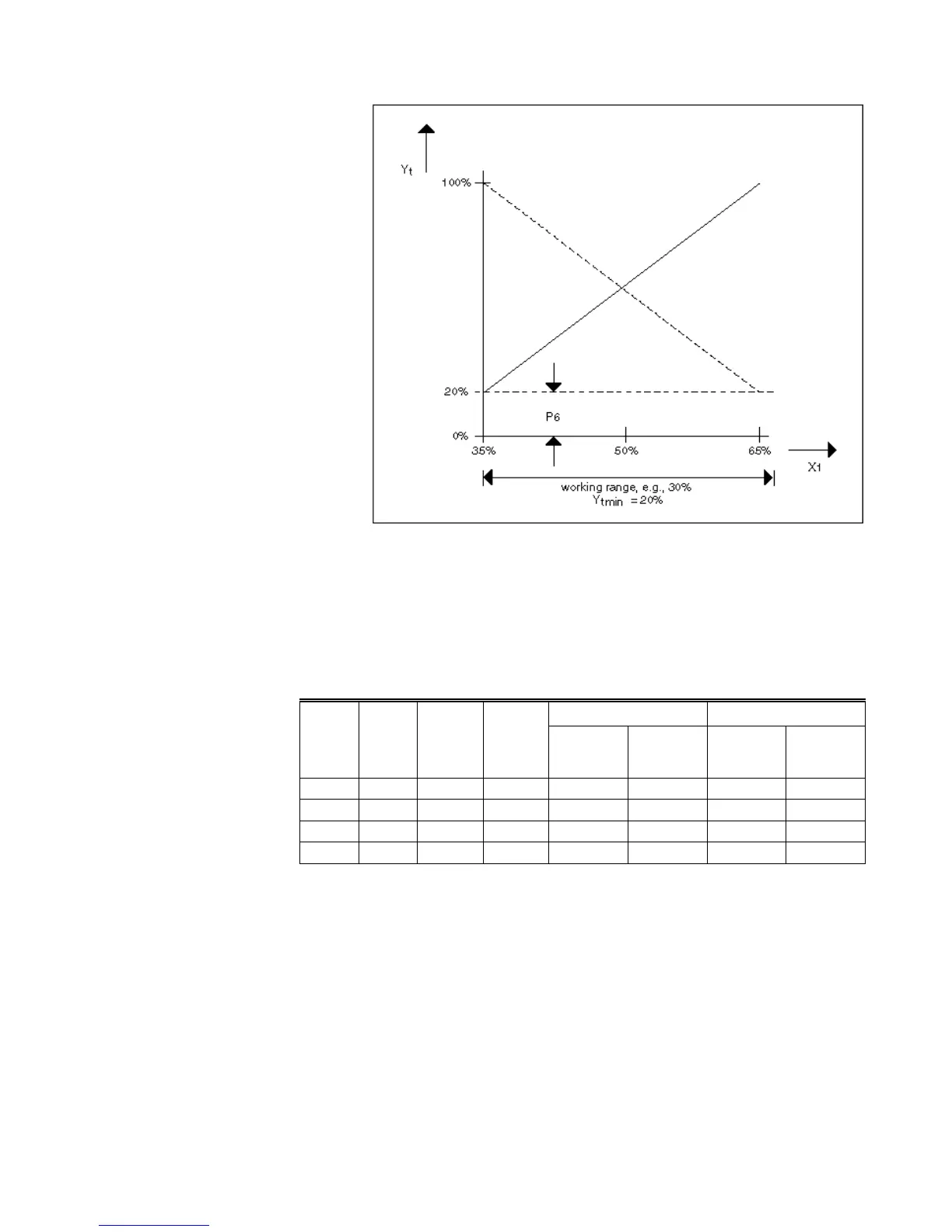
Minimum limitation with regenerative transfer operation:
Module 5 Moisture Recovery
This module functions the same as Module 4 except that it calculates a signal from
the humidity controller (X2). The module outputs continuous positioning signal YF.
Module 6 Selection Logic
This module evaluates the results from Modules 1 through 5 and decides whether to
transmit positioning signal YT or YF to output Y of the ECO control icon. The
following table summarizes module logic.
h
AL
>h
AbL
h
AL
<h
AbL
Need
for
Heating
Need
for
Cooling
Reduce
Humidity
Increase
Humidity
Cooling
more
expensive
Heating
more
expensive
Cooling
more
expensive
Heating
more
expensive
0 1 0 1 MAX MAX MIN MIN
0 1 1 0 MAX MAX MIN MIN
1 0 0 1 MIN MIN MAX MAX
1 0 1 0 MAX MIN MIN MAX
A zero in the table indicates no need. A one indicates a need.
MAX indicates selection of the maximum of either the YT or YF signal for the Y
signal.
MIN indicates selection of the minimum of either the YT or YF signal for the Y signal.
In a partial air conditioning system (only temperature control), this module just sends
the YT signal from Module 4 to output Y.
The following diagrams illustrate table output (MIN and MAX for temperature and
humidity).
MAX Temperature Controller

 Loading...


