Electrical Characteristics
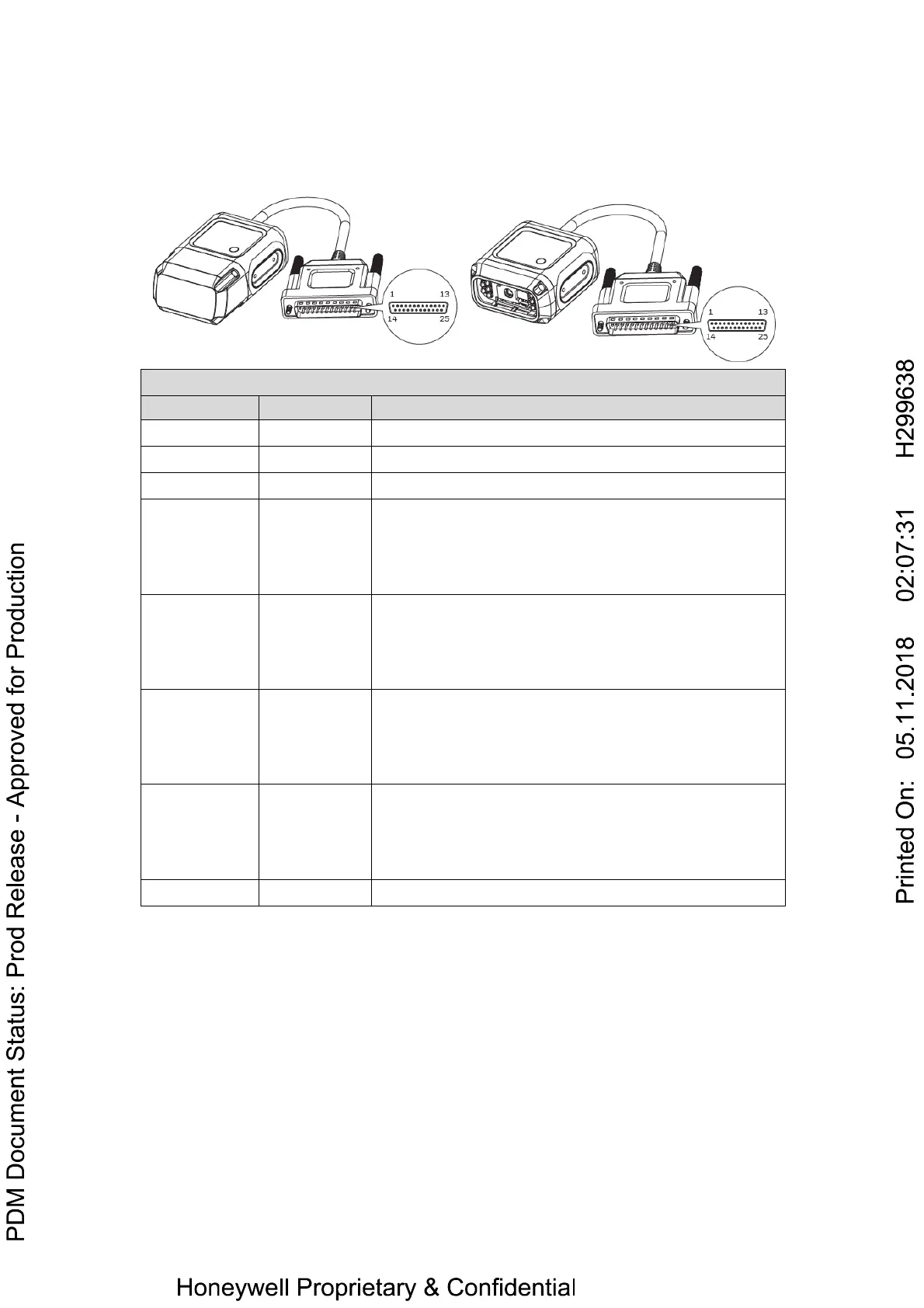
HF800 D-sub 25pin male connector
Power, COM and I/O Connector Pinout
Power supply input(10VDC-30VDC)
RS232_TX
RS232_RX
RS232_RTS
RS232_CTS
TXD(output)
RXD(input)
RTS(output)
CTS(input)
External Input channel 2 A
External Input channel 2 B
External Input channel 1 A
External Input channel 1 B
Output 1 +
Output 1 -
Output 2 +
Output 2 -
RS485_Z
RS485_Y
RS485_A
RS485_B
RX-(RS422 RX- only) (input)
RX+(RS422 RX+ only) (input)
T/R+(RS485 data+ and RS422 TX+)
T/R-(RS485 data- and RS422 TX-)
Output
Two digital outputs (Output1, Output2) are available, with the protection of 2
optocouplers. The maximum V
CE
of the optocoupler is 30VDC, maximum continuous
current is 50mA. User should adjust the VDD and the load resistance to make sure
the current is less than 50mA, and VDD is less than 30VDC. There are two Zener
diodes paralleled with the Output Pin, and the Breakdown Voltage of the diode is
5.6V, therefore, if the external power supply which directly connected to the output
pin is higher than 6V, the voltage will be clamped to 5.6V. User could use these 2
outputs to control beeper, external illumination LEDs.
Typical use case:
 Loading...