68 Thor VM1 with Microsoft Windows Embedded Standard 2009 User Guide
•For 36VDC input, use the 4A fuse from the kit or a slow blow fuse that has a DC
voltage rating greater than 36VDC.
•For 48VDC input, use the 3A fuse from the kit or a slow blow fuse that has a DC
voltage rating greater than 48VDC.
Note: For North America, a UL Listed fuse is to be used.
Power Cable Identification
The DC power cable is included with the dock and is one of the two styles below:
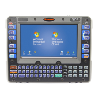
Power cable with right angle connector and 6 wires:
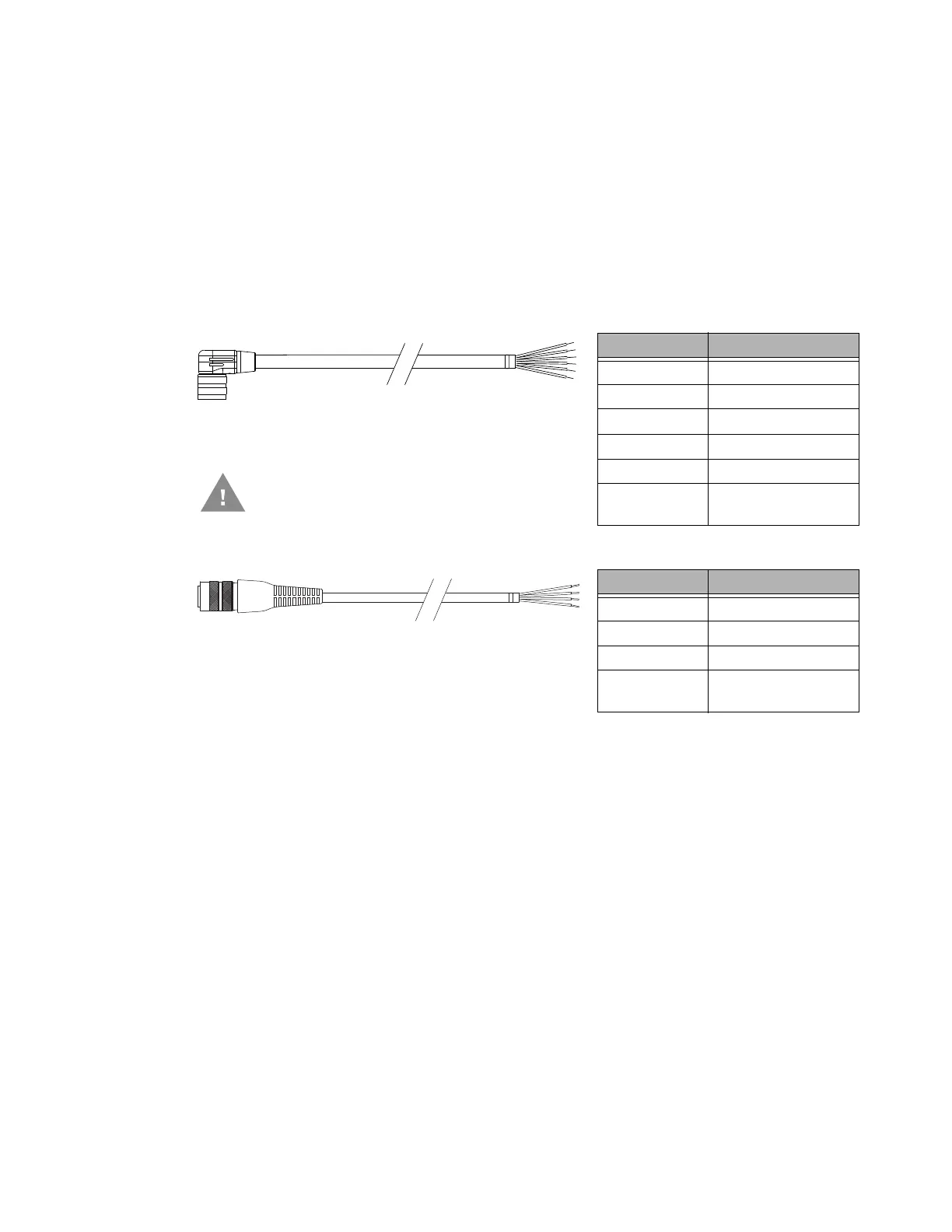
Power cable with straight connector and 4 wires:
Note: Correct electrical polarity is required for safe and proper installation. See the figures below
for additional wire color-coding specifics.
The Thor VM1 DC input wires (Red, Red/White DC+ and Black, Black/White DC-) and
the Blue ignition input wire are galvanically isolated. The Green ground input is used for
electrostatic discharge (ESD) protection.
Vehicle 10-60VDC Direct Power Connection
1. The Thor VM1 must not be mounted in the dock. The power switch on the dock must
be turned Off. The power cable must be UNPLUGGED from the dock.
2. While observing the Fuse Requirements, connect the power cable as close as
possible to the actual battery terminals of the vehicle (if using unswitched power).
3. Use proper electrical and mechanical fastening means for terminating the cable.
Properly sized “crimp” type electrical terminals are an accepted method of
termination. Please select electrical connectors sized for use with 20AWG
(0.81mm2) conductors.
4. Refer to the wiring diagrams following this section for wire colors and connections:
Wire Color Connection
Red DC + (10-60 VDC)
Red/White DC + (10-60 VDC)
Black DC -
Black/White DC -
Twist the red and red/white wires together and
twist the black and black/white wires together
before connecting to vehicle power.
Green Ground
Blue Ignition Input
(optional)
Wire Color Connection
Red DC + (10-60 VDC)
Black DC -
Green Ground
Blue Ignition Input
(optional)
 Loading...