80 Thor VM1 with Microsoft Windows Embedded Standard 2009 User Guide
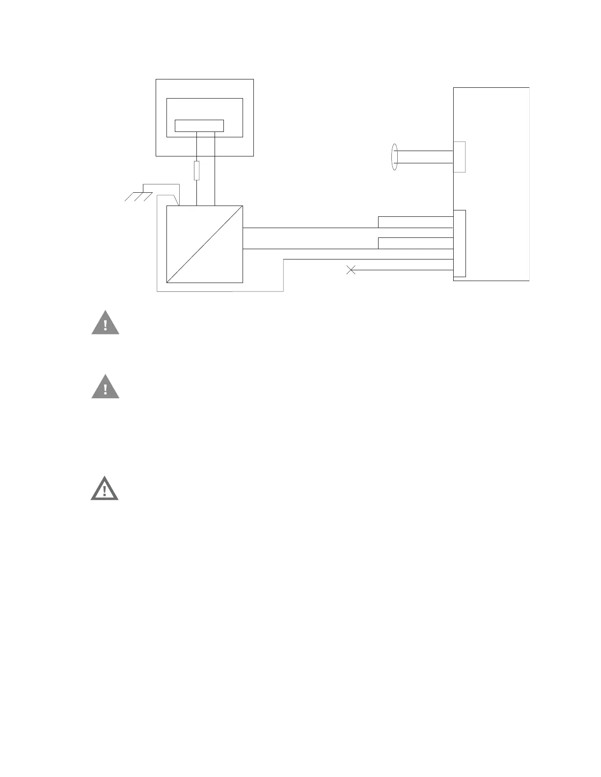
Wiring Diagram
• GND must be connected to the vehicle chassis ground.
• GND is connected to the vehicle chassis ground, which can also be battery negative.
Fuse Requirements
•For all voltages, use the 3A fuse from the kit or a slow blow fuse that has a DC voltage
rating greater than the vehicle input voltage.
Note: For North America, a UL Listed fuse is to be used.
Main Switch
Circular
Power
Connector
on Dock
V
IN-
V
O-
-Vo
+Vo
COM1 or COM2
Connector
on Dock
VO+
V
IN+
GND
User supplied serial
cable for optional
screen blanking
connection,
see below
Existing Circuitry on Vehicle
Forklift Battery
DC/DC
Power
Supply
Fuse - See
Warning
statement below
See
statement
below
(not connected)
Black
Green
Blue
Red
Red/White (if present)
Black/White (if present)
Quick Mount
Smart Dock
Caution: For battery powered vehicles:
Caution: For internal combustion engine powered vehicles:
Warning: For proper and safe installation, the input power cable must be
connected to a fused circuit on the vehicle. If the supply
connection is made directly to the battery, the fuse should be
installed in the positive lead within 5 inches of the battery’s
positive (+) terminal. Use VM3055FUSE (or equivalent) to
install the fuse as shown below:
 Loading...