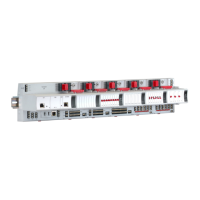
XLS80e Fire Alarm Control Panels
114Honeywell, Issue 9
March 2007
See note below
13 Sensitivity & Alarm Delay
Recommendations
This section provides guidance in carrying out
the procedures described in Sections 5.1.2.4,
5.1.2.5 and 5.1.4.5. It should be consulted in
particular when modules are to have their
sensitivities and delays adjusted, since the
parameters vary according to the application.
13.1 Analogue Sensors Sensitivity
The sensitivity parameters of analogue sensors,
except Photo/Thermal (MULTI), are factory-set
so that the system complies with appropriate
standards (in particular EN54 Part 7). They will
not normally need adjustment except in special
circumstances. The factory settings (common
to all types of analogue sensor) are:
Fire Alarm: L5 (above)
Pre-Alarm: L5 (above)
Note: If the percentage values listed move in
the direction indicated in brackets a Fire/
Pre-alarm condition will exist.
The allowable adjustment ranges are L1 to L9
for Fire Alarm and for Pre-alarm (these ranges
do not overlap). MULTI sensors have a
different range as given in Section 5.1.3. MCS
sensors are described in Section 5.1.3.2.
13.2 Analogue Device Verification
To minimise the occurrence of unwanted alarm
or fault indications, a verification delay is
recommended between signals from the
device and the fire/pre-alarm/fault condition.
The device alarm and fault verification delays are
factory set as follows:
Device Type Alarm Verification Delays
Default Maximum
ION 3 5
PHOTO 20 30
THERMAL 3 5
MULTI/MCS 3 5
Module types:
MCP, CDI, ZMX 0 2
MONITOR 1 100
Device Type Pre-Alarm/
Fault Verification Delays
Default Maximum
All Sensors 20 100
MONITOR 20 100
SPRINKLER 40 100
monitor
CAUTION!
If the percentage values vary
in the direction indicated in
brackets a FIRE/PRE-
ALARM condition exists.
A lower threshold setting on
the FIRE or PRE-ALARM
makes the sensor more
sensitive, whereas a higher
threshold makes it less so.

 Loading...


