69 Honeywell, Issue 9
March 2007
XLS80e Fire Alarm Control Panels
7.6.2 Output Definitions
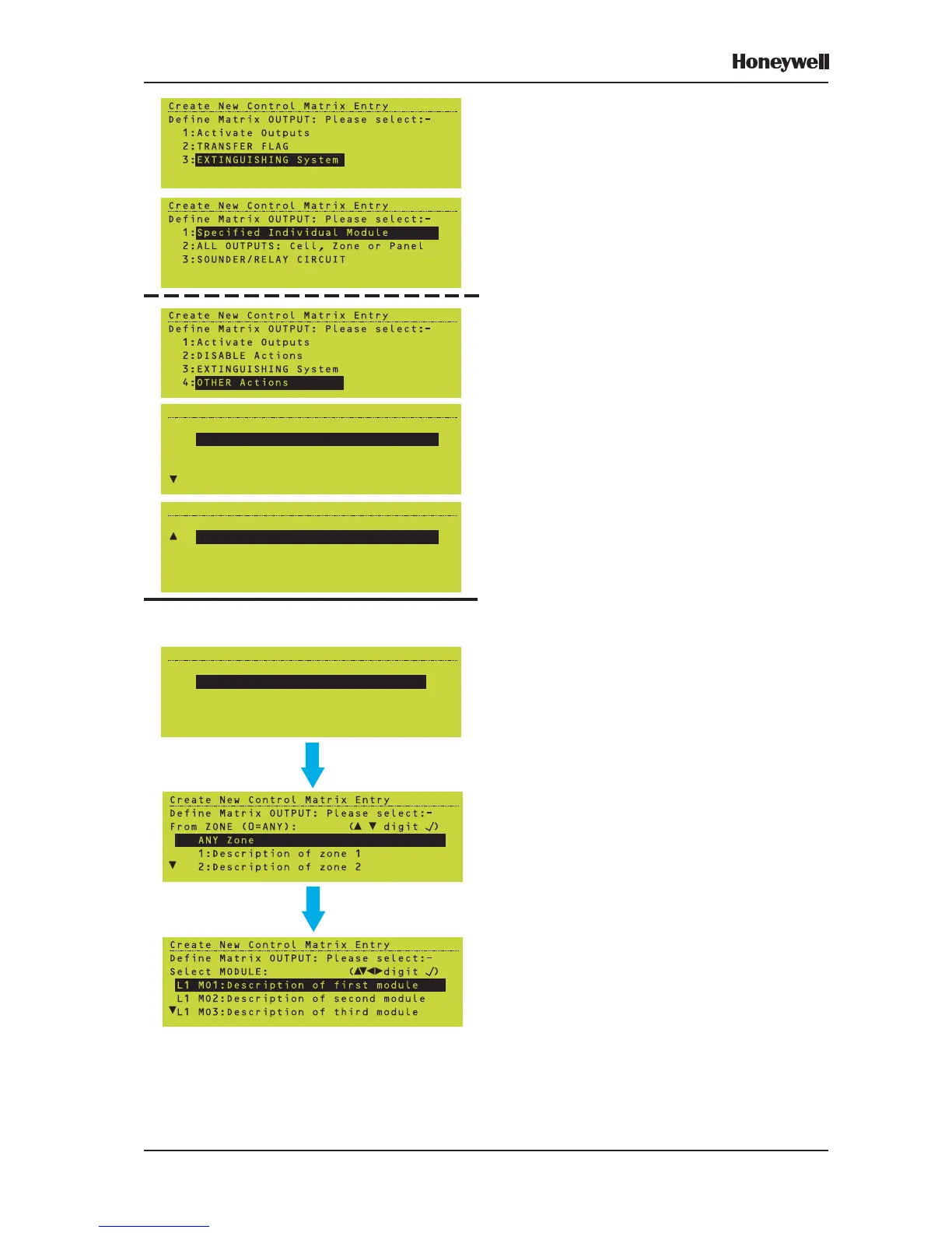
Select Activate Outputs to specify immediate
action or TRANSFER FLAG when a delayed
action is required (used with a time-of-day
function).
If you selected TRANSFER FLAG, enter a
number. If Activate Outputs was selected,
choose the output from the list. Subsequent
steps depend upon which output is selected.
The Extinguishing System output definition is
described in Section 7.6.2.4.
‘DISABLE Actions is only available if the INPUT
is NON-FIRE ACTIVATION or TRUE. ‘Other
Actions’ is only available if the INPUT is
NON-FIRE ACTIVATION. It provides eight
output options as shown.
7.6.2.1 Specified Individual Module
From the Activate Outputs menu, select
option 1 to specify an individual module as the
output.
1 Select the zone to display a list of modules
in that zone (or ANY Zone if the zone is not
known).
2 Select the required module from the list.
Note: If you select an input module (e.g. an
MCP) as an output, the Control Matrix
action will only be to turn on that
module’s LED.
Note: A Loop Booster can only be selected as
an individual device if the input is NON-
FIRE ACTIVE and the output is
‘DISABLE Actions’. If the Loop Booster’s
zone is included in an output the other
devices in the zone are activated but the
Loop Booster is not, even if the
Restricted by Type is ALL OUTPUT
MODULES. Operation of the Loop
Booster is controlled automatically by
the panel and not by the Control Matrix
rules.
3 Pulsing, Delay and Time-of-Day options
become available (see Section 7.6.2.2)
depending upon the Control Matrix input
definition (Time-of-Day is always provided).
ACTIVATE OUTPUTS:
IF OPTION 1 (INDIVIDUAL MODULE) IS CHOSEN:
Create New Control Matrix Entry
Define Matrix OUTPUT: Please select:-
1:
2:SILENCE SOUNDERS
3:SYSTEM RESET
4:TRANSFER FLAG
MUTE INTERNAL BUZZER
Create New Control Matrix Entry
Define Matrix OUTPUT: Please select:-
5:
6:System in DAY mode
7:Extend Investigation Delay
8:OVER-RIDE Sounder/Investig. Delays
System in NIGHT mode
Create New Control Matrix Entry
Define Matrix OUTPUT: Please select:-
1:
2:ALL OUTPUTS: Cell, Zone or Panel
3:SOUNDER/RELAY CIRCUIT
4:Virtual Output Point
Specified Individual Module
 Loading...


