36
• The workbench or floor is sturdy enough to support the weight of the chassis and its accessories.
• The workbench or floor is reliably grounded.
Installation procedures
IMPORTANT:
llow 0.8 m (2.62 ft) of clearance around the switch for heat dissipation.
To install the switch:
1. Hold the two sides of the switch and steadily move the switch to the workbench.
2. Lift the switch a little higher than the workbench and put it on the workbench.
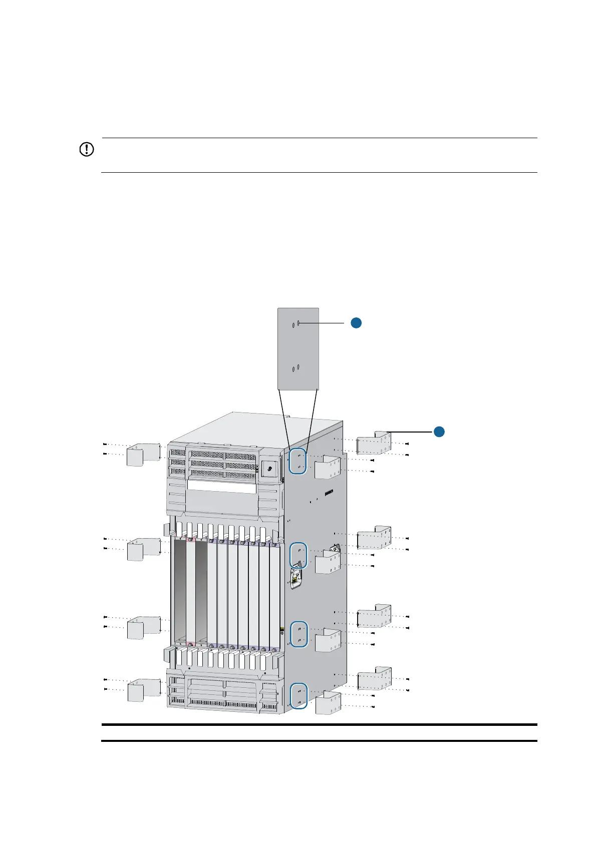
3. Install the mounting brackets on the switch and fasten the screws, as shown in Figure 34 (optional).
Each circled area in Figure 34 shows tw
o rows of installation holes. You can select either row of
a circled area to install the mounting brackets.
Figure 34 Installing the mounting brackets
(1) Mountin
bracket installation holes (2) Mountin
bracket
1
2
 Loading...