19
Power supply
To meet the power supply requirements:
1. Calculate the system power consumption.
2. Select power supplies according to the system power consumption and power supply mode.
To ensure normal operation of the switch, make sure the maximum output power of the power
supplies is greater than the system power consumption of the switch (reserve certain power for
redundancy). After determining the system power consumption and power supply mode (AC or
DC power supply), you can select power supplies as needed.
3. Verify that the power source on the installation site meets the requirements of the power supplies.
Make sure the power source of the installation site is steady and can meet the requirements of the
power supplies, including the input method and rated input voltage.
For the power consumption and power supply specifications of the switch, see "Appendix A Technical
specifications."
Cooling
Plan the installation site for adequate ventilation.
• Leave at least 10 cm (3.94 in) of clearance around the air intake vents and exhaust vents.
• Equip a good cooling system for the cabinet to install the switch.
• Equip a good cooling system for the installation site.
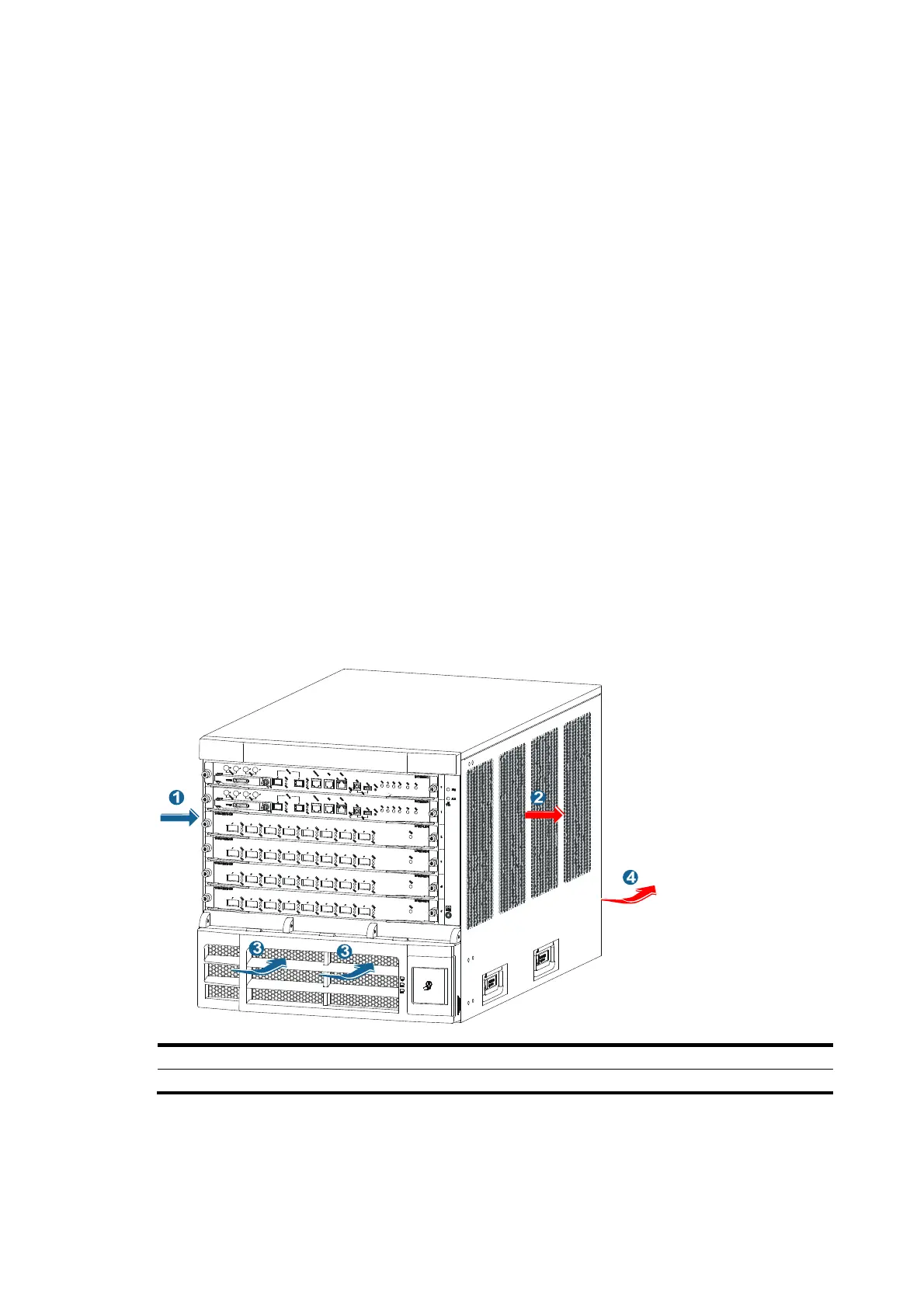
Figure 17, Figure 18, and Figure 19 s
how the ventilation of the 12504, 12508, and 12518.
Figure 17 Airflow through a 12504 chassis
(1)
ir intake direction of the chassis (2)
ir exhaust direction of the chassis
(3)
ir intake direction of the power supplies (4)
ir exhaust direction of the power supplies
 Loading...