42
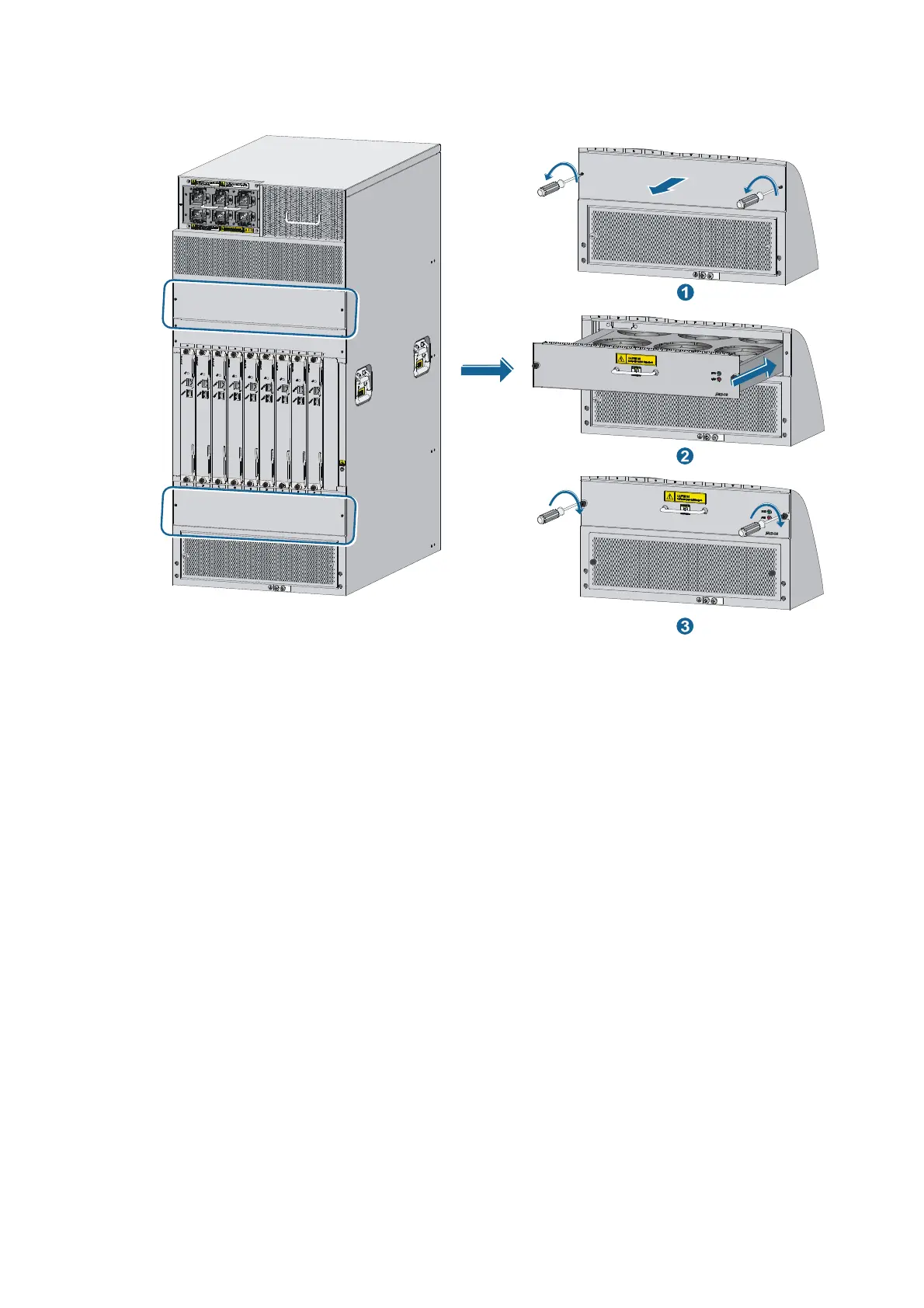
Figure 40 Installing a fan tray (for the 12508 and 12518)
Installing a card
On a 12504, install at least one MPU, one LPU, and three switching fabric modules. On a 12508 or
12518, install at least one MPU, one LPU, and seven switching fabric modules.
The 12500 does not support intermixing of the MPU, LPU, and switching fabric modules.
Use one of the following positions to install the card:
• Install MPUs, Ethernet interface cards , and OAA cards at the front of the switch chassis. Slot 0 and
Slot 1 are for MPUs and other slots (slots 2 to 5 for the 12504, slots 2 to 9 for the 12508, and slots
2 to 19 for the 12518) are for Ethernet interface cards and OAA cards.
• Install switching fabric modules in the switching fabric module slots (slots 6 to 9 for the 12504, slots
10 to 18 for the 12508, and slots 20 to 28 for the 12518) at the rear of the chassis.
You can install MPUs, LPUs, and switching fabric modules in a similar way. This section describes how to
install an MPU as an example.
Installation preparation
1. Wear an ESD-preventive wrist strap and make sure it is properly grounded.
2. Remove the blank panel (if any) from the slot to be used.
3. Unpack the card to be installed.
 Loading...