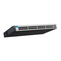
56
NOTE:
• The 12500 routing switches provides a command line interface (CLI). For more information about the
CLI, see
HP 12500 Routing Switch Series Fundamentals Configuration Guide.
• The output depends on your switch model.
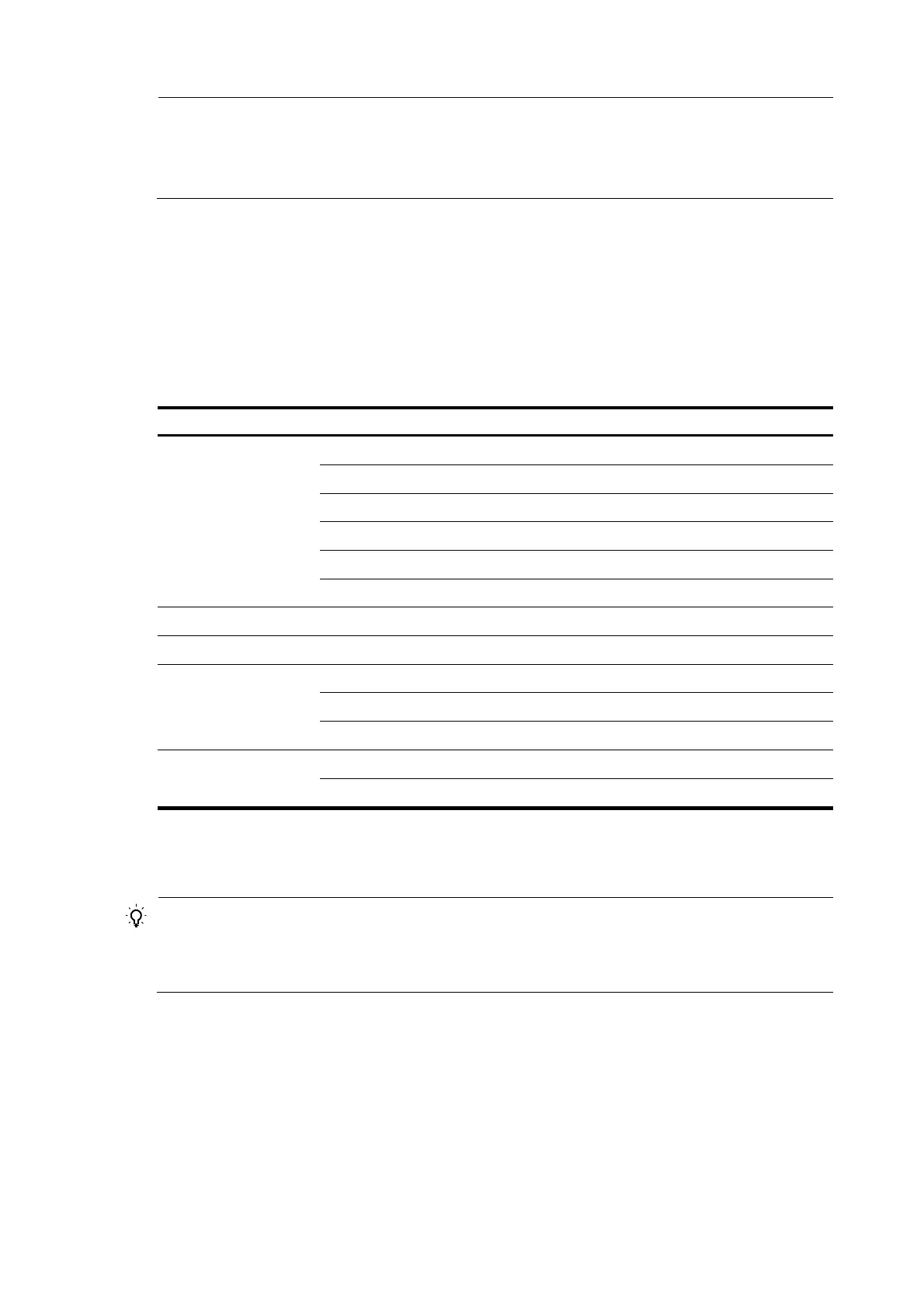
Verification after power-on
HP recommends that you check the following conditions after the switch is powered on:
• The cooling system is operating. You should be able to hear fan rotation noise and feel air being
blown out.
• All the system LEDs on the MPUs are functioning properly.
Table 15 LED status when the switch operates normally
Module LED Status
MPU
SFC (red and green) Flashing green
LC (red and green) Flashing green
FAN (red and green) Flashing green
PWR (red and green) Flashing green
ACT (green) Steady on
RUN (red and green) Flashing green
LPU RUN (red and green) Flashing green
Switching fabric module RUN (red and green) Flashing green
Power monitor module
RUN (green) Steady on
MAJOR (red) Off
MINOR (yellow) Off
Fan
RUN (green) Flashing
ALM (red) Off
Connecting the switch to the network
TIP:
fter connectin
the switch to the network, you can use the ping or tracert command to check the
interoperability between the switch and network. For more information, see
HP 12500 Routing Switch
Series Network Management and Monitoring Command Reference
.
Connecting the switch to the network through the AUX port
You need an AUX cable when configuring a switch with the remote modem dial-up approach.
 Loading...