1
Configuring Ethernet interfaces
Ethernet interface naming conventions
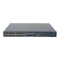
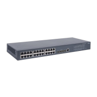
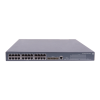
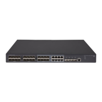
The GE and 10-GE interfaces on the HP 5120 EI switches are named in the format of interface-type
A/B/C, where the following definitions apply:
• A—Represents the ID of the switch in an IRF fabric. If the switch is not assigned to any IRF fabric, A
uses 1.
• B—Represents a slot number on the switch. It uses 0 for fixed interfaces, 1 for interfaces on interface
expansion card 1, and 2 for interfaces on interface expansion card 2.
• C—Represents the number of an interface on a slot.
Configuring a combo interface
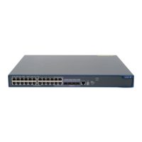
A combo interface is a logical interface that comprises one optical (fiber) port and one electrical (copper)
port. The two ports share one forwarding interface, so they cannot work simultaneously. When you
enable one port, the other is automatically disabled.
The fiber combo port and cooper combo port are Ethernet interfaces. They have their own separate
interface views, in which you can activate the fiber or copper combo port and configure other port
attributes such as the interface rate and duplex mode.
Configuration prerequisites
Before you configure a combo interface, complete the following tasks:
• Use the display port combo command to identify the combo interfaces on your switch and identify
the two physical ports that compose each combo interface.
• Use the display interface command to determine, of the two physical ports that compose a combo
interface, which is the fiber combo port and which is the copper combo port. If the current port is
the copper port, the output will include "Media type is twisted pair, Port hardware type is
1000_BASE_T". If the current port is the fiber port, the output will not include the information
mentioned above.
Changing the active port of a combo interface
To change the active port of a double combo interface:
Ste
Command
Remarks
1. Enter system view.
system-view N/A
2. Enter Ethernet
interface view.
interface interface-type
interface-number
N/A
 Loading...
