143
Task Command
Remarks
Display the mapping between an
isolate-user-VLAN and its secondary
VLANs.
display isolate-user-vlan
[ isolate-user-vlan-id ] [ | { begin |
exclude | include } regular-expression ]
Available in any view
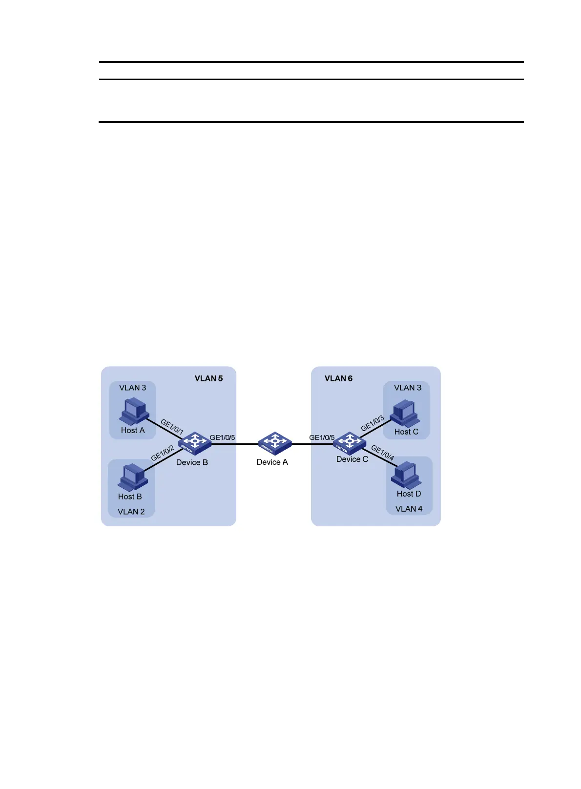
Isolate-user-VLAN configuration example
Network requirements
As shown in Figure 46:
• Connect Device A to downstream devices Device B and Device C.
• Configure VLAN 5 on Device B as an isolate-user-VLAN, assign the uplink port GigabitEthernet
1/0/5 to VLAN 5, and associate VLAN 5 with secondary VLANs VLAN 2 and VLAN 3. Assign
GigabitEthernet 1/0/2 to VLAN 2 and GigabitEthernet 1/0/1 to VLAN 3.
• Configure VLAN 6 on Device C as an isolate-user-VLAN, assign the uplink port GigabitEthernet
1/0/5 to VLAN 6, and associate VLAN 6 with secondary VLANs VLAN 3 and VLAN 4. Assign
GigabitEthernet 1/0/3 to VLAN 3 and GigabitEthernet 1/0/4 to VLAN 4.
• As far as Device A is concerned, Device B only has VLAN 5 and Device C only has VLAN 6.
Figure 46 Network diagram
Configuration procedure
The following part provides only the configuration on Device B and Device C.
1. Configure Device B:
# Configure the isolate-user-VLAN.
<DeviceB> system-view
[DeviceB] vlan 5
[DeviceB-vlan5] isolate-user-vlan enable
[DeviceB-vlan5] quit
# Create secondary VLANs.
[DeviceB] vlan 2 to 3

 Loading...


