140
Configuring an isolate-user-VLAN
Overview
An isolate-user-VLAN uses a two-tier VLAN structure. In this approach, the following types of VLANs,
isolate-user-VLAN and secondary VLAN, are configured on the same device.
The following are the characteristics of the isolate-user-VLAN implementation:
• Isolate-user-VLANs are mainly used for upstream data exchange. An isolate-user-VLAN can be
associated with multiple secondary VLANs. As the upstream device identifies only the
isolate-user-VLAN and not the secondary VLANs, network configuration is simplified and VLAN
resources are saved.
• You can isolate the Layer 2 traffic of different users by assigning the ports connected to them to
different secondary VLANs. To enable communication between secondary VLANs associated with
the same isolate-user-VLAN, you can enable local proxy ARP on the upstream device (for example,
Device A in Figure 45) to r
ealize Layer 3 communication between the secondary VLANs.
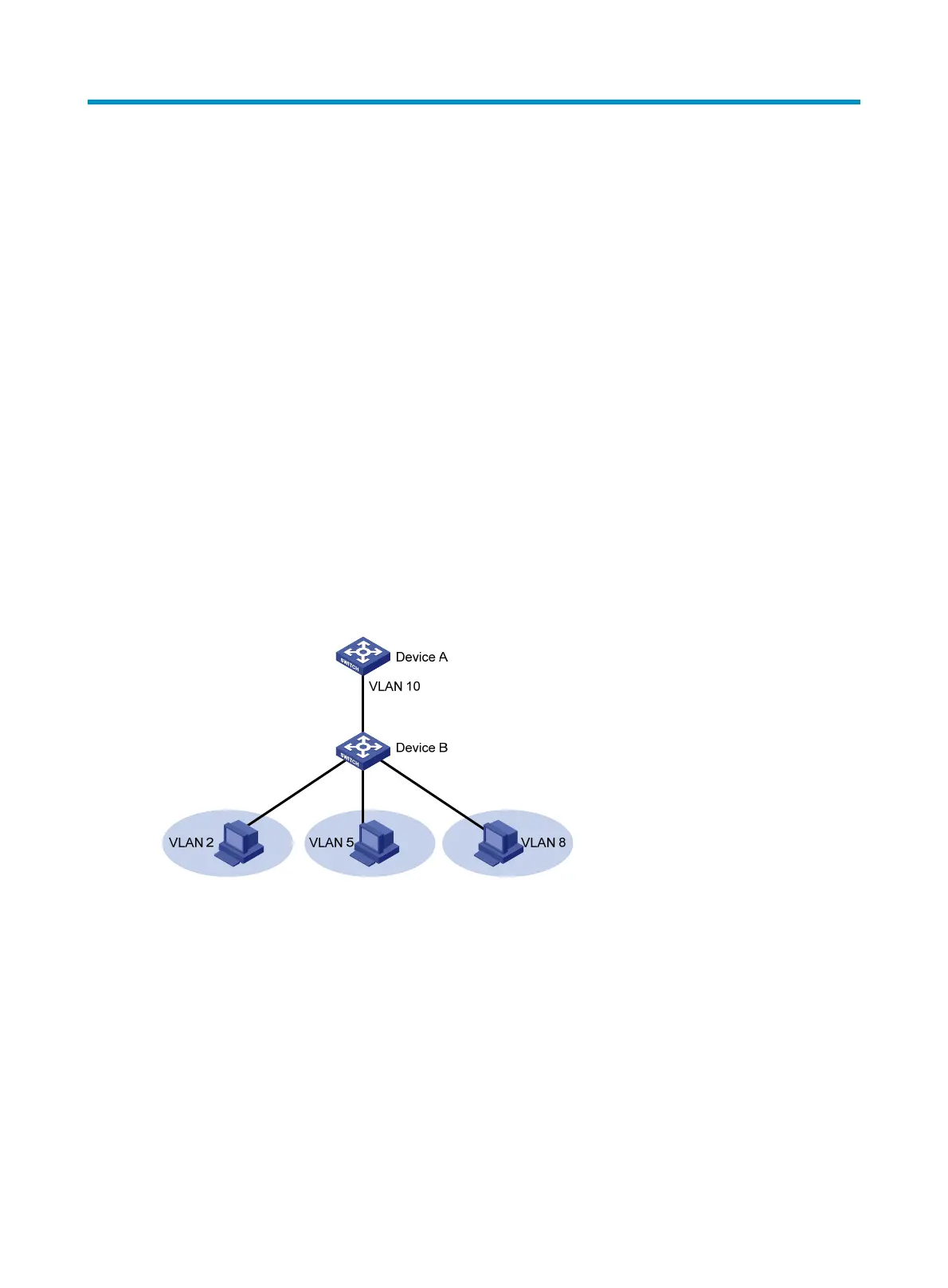
As shown in Figure 45,
the isolate-user-VLAN function is enabled on Device B. VLAN 10 is the
isolate-user-VLAN. VLAN 2, VLAN 5, and VLAN 8 are secondary VLANs associated with VLAN 10 and
are invisible to Device A.
Figure 45 An isolate-user-VLAN example
To configure an isolate-user-VLAN, complete the following tasks:
1. Configure the isolate-user-VLAN.
2. Configure the secondary VLANs.
3. Associate the isolate-user-VLAN with the specified secondary VLANs.
4. Configure uplink and downlink ports:
{ Configure the uplink ports, for example, the port connecting Device B to Device A in Figure 45,
to operate in promiscuous mode in the specified VLAN, so that the uplink ports can be added
to the specified isolate-user-VLAN and the secondary VLANs associated with the
isolate-user-VLAN automatically.

 Loading...


