117
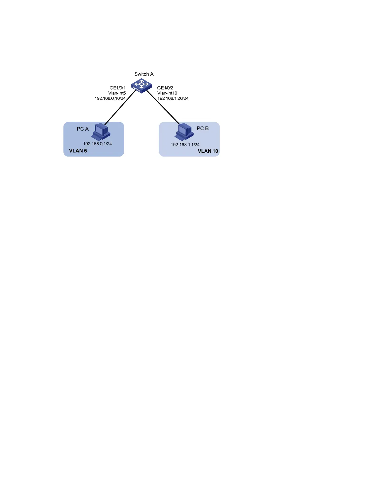
Configure VLAN interfaces on Switch A and configure the PCs to enable Layer 3 communication
between the PCs.
Figure 39 Network diagram
Configuration procedure
1. Configure Switch A:
# Create VLAN 5 and assign GigabitEthernet 1/0/1 to it.
<SwitchA> system-view
[SwitchA] vlan 5
[SwitchA-vlan5] port GigabitEthernet 1/0/1
# Create VLAN 10 and assign GigabitEthernet 1/0/2 to it.
[SwitchA-vlan5] vlan 10
[SwitchA-vlan10] port GigabitEthernet 1/0/2
[SwitchA-vlan10] quit
# Create VLAN-interface 5 and configure its IP address as 192.168.0.10/24.
[SwitchA] interface vlan-interface 5
[SwitchA-Vlan-interface5] ip address 192.168.0.10 24
[SwitchA-Vlan-interface5] quit
# Create VLAN-interface 10 and configure its IP address as 192.168.1.20/24.
[SwitchA] interface vlan-interface 10
[SwitchA-Vlan-interface10] ip address 192.168.1.20 24
[SwitchA-Vlan-interface10] return
2. Configure the default gateway of PC A as 192.168.0.10.
3. Configure the default gateway of PC B as 192.168.1.20.
Verifying the configurations
1. The PCs can ping each other.
2. Display brief information about Layer 3 interfaces on Switch A to verify the configuration.
<SwitchA> display ip interface brief
*down: administratively down
(s): spoofing
Interface Physical Protocol IP Address Description
Vlan-interface5 up up 192.168.0.10 Vlan-inte...
Vlan-interface10 up up 192.168.1.20 Vlan-inte...

 Loading...


