129
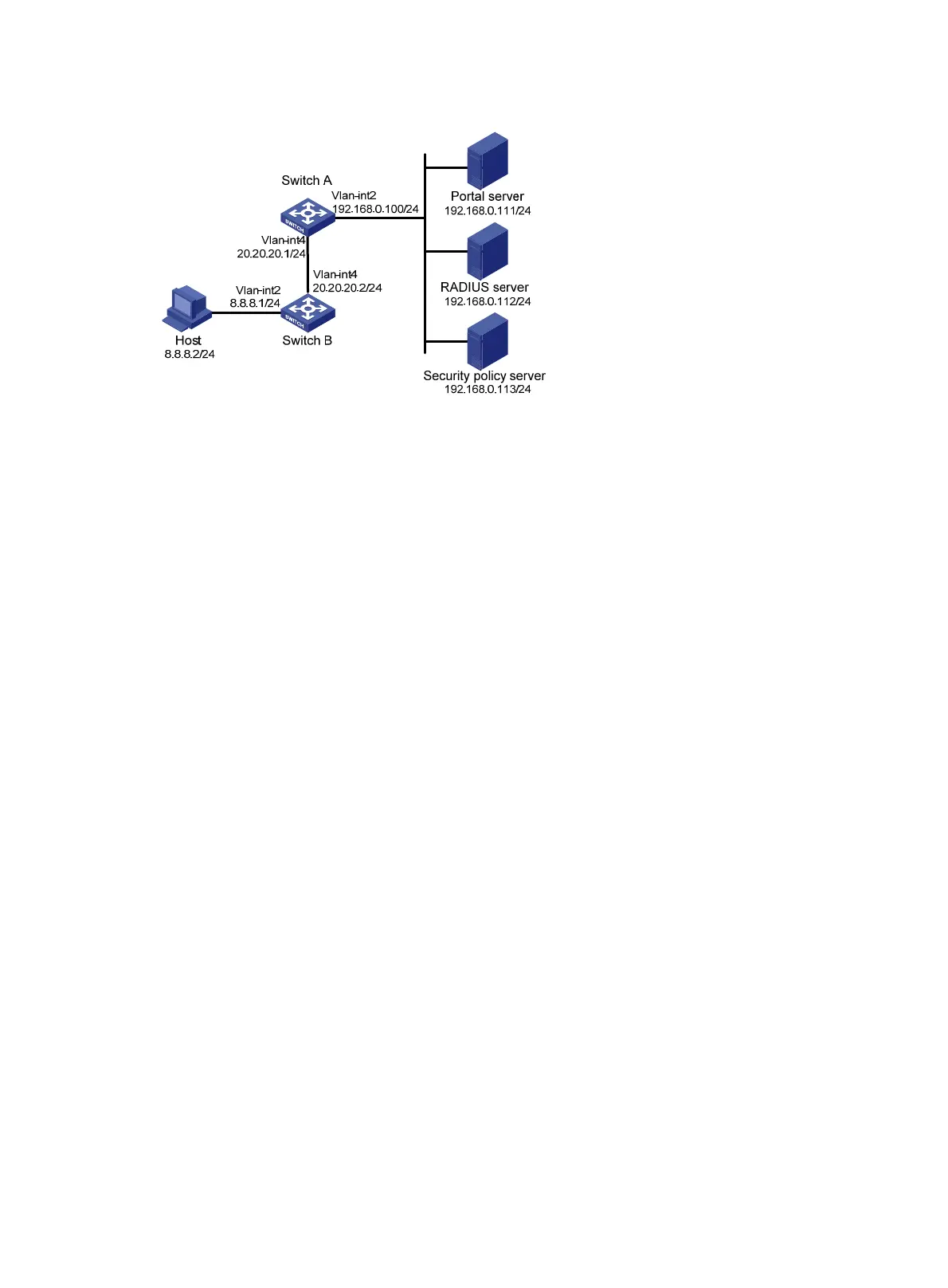
Figure 52 Network diagram
Configuration prerequisites and guidelines
• Configure IP addresses for the switch and servers as shown in Figure 52 and make sure the host,
switch, and servers can reach each other.
• Configure the RADIUS server properly to provide authentication and accounting functions.
• Make sure the IP address of the portal device added on the portal server is the IP address
(20.20.20.1) of the switch's interface connecting the host. The IP address group associated with the
portal device is the subnet of the host (8.8.8.0/24).
Configuration procedure
Perform the following tasks on Switch A.
1. Configure a RADIUS scheme:
# Create a RADIUS scheme named rs1 and enter its view.
<SwitchA> system-view
[SwitchA] radius scheme rs1
# Specify the primary authentication server and primary accounting server, and configure the keys
for communication with the servers.
[SwitchA-radius-rs1] primary authentication 192.168.0.112
[SwitchA-radius-rs1] primary accounting 192.168.0.112
[SwitchA-radius-rs1] key accounting simple radius
[SwitchA-radius-rs1] key authentication simple radius
[SwitchA-radius-rs1] user-name-format without-domain
# Specify the security policy server.
[SwitchA-radius-rs1] security-policy-server 192.168.0.113
[SwitchA-radius-rs1] quit
# Enable RADIUS session control.
[SwitchA] radius session-control enable
2. Configure an authentication domain:
# Create an ISP domain named dm1 and enter its view.
[SwitchA] domain dm1
# Configure AAA methods for the ISP domain.
[SwitchA-isp-dm1] authentication portal radius-scheme rs1
 Loading...


