351
Manual-mode MFF configuration example in a ring network
Network requirements
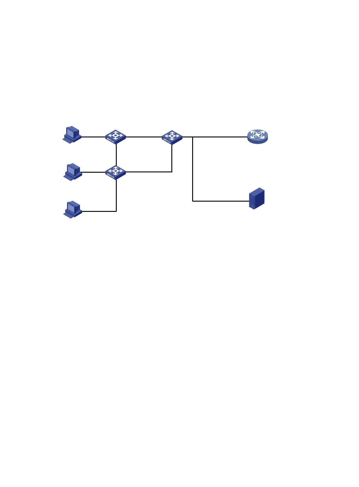
As shown in Figure 119, all the devices are in VLAN 100, and the switches form a ring. Hosts A, B, and
C are assigned IP addresses manually.
Configure MFF to isolate the hosts at Layer 2 and allow them to communicate with each other through the
gateway at Layer 3.
Figure 119 Network diagram
Configuration procedure
1. Assign IP addresses to the hosts and the gateway. (Details not shown.)
2. Configure Switch A:
# Enable STP globally to make sure STP is enabled on interfaces.
[SwitchA] stp global enable
# Configure manual-mode MFF on VLAN 100.
[SwitchA] vlan 100
[SwitchA-vlan100] mac-forced-forwarding default-gateway 10.1.1.100
# Specify the IP address of the server.
[SwitchA-vlan100] mac-forced-forwarding server 10.1.1.200
# Enable ARP snooping on VLAN 100.
[SwitchA-vlan100] arp snooping enable
[SwitchA-vlan100] quit
# Configure Ten-GigabitEthernet 1/0/2 and Ten-GigabitEthernet 1/0/3 as network ports.
[SwitchA] interface ten-gigabitethernet 1/0/2
[SwitchA-Ten-GigabitEthernet1/0/2] mac-forced-forwarding network-port
[SwitchA-Ten-GigabitEthernet1/0/2] quit
[SwitchA] interface ten-gigabitethernet 1/0/3
[SwitchA-Ten-GigabitEthernet1/0/3] mac-forced-forwarding network-port
3. Configure Switch B:
# Enable STP globally to make sure STP is enabled on interfaces.
[SwitchB] stp global enable
Switch A
Switch C Gateway
Switch B
XGE1/0/5
XGE1/0/6
XGE1/0/3
XGE1/0/1 XGE1/0/2
XGE1/0/10
XGE1/0/8 XGE1/0/9
Server
XGE1/0/7
XGE1/0/4
Host C
10.1.1.3/24
Host B
10.1.1.2/24
Host A
10.1.1.1/24
10.1.1.100/24
10.1.1.200/24
 Loading...


