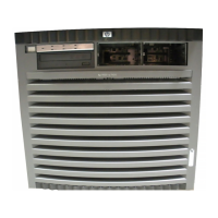
Figure 1-2 HP 9000 rp7420 server (without front bezel)
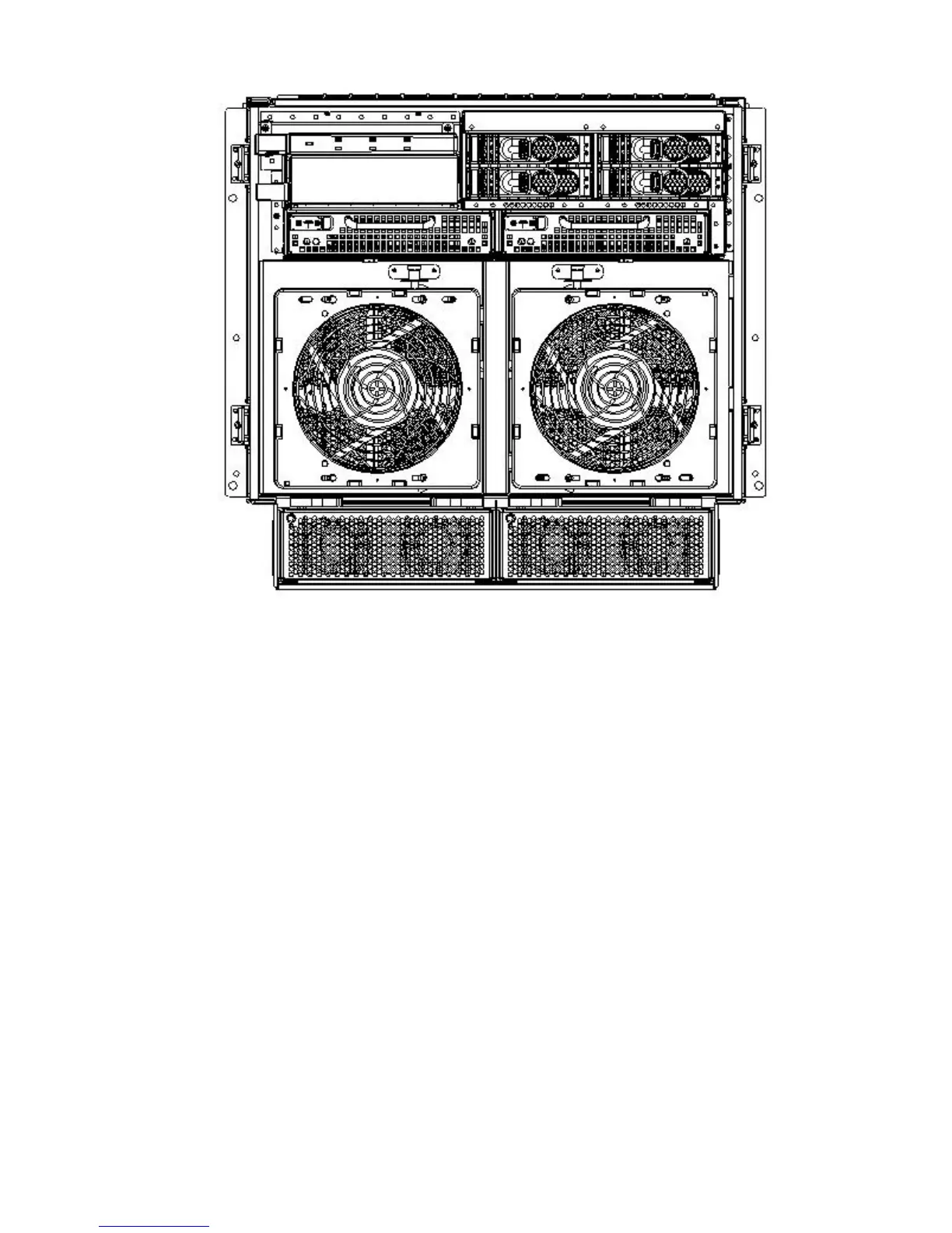
System Backplane
The system backplane is comprised of the system clock generation logic, the system reset
generation logic, DC-to-DC converters, power monitor logic, and two Local Bus Adapter (LBA)
link-to-PCI converter ASICs. It also includes connectors for attaching the cell boards, the PCI-X
backplane, Management Processor (MP) Core I/O MP/SCSI boards, SCSI cables, bulk power,
chassis fans, the front panel display, intrusion switches, and the system scan card. Unlike the
Superdome or rp8400 servers, there are no Crossbar Chips (XBC) on the system backplane. The
“crossbar-less” back-to-back Cell Controller (CC) connection increases performance and reduces
costs.
Only half of the MP Core I/O board set connects to the system backplane. The MP/SCSI boards
plug into the backplane, while the LAN/SCSI boards plug into the PCI-X backplane.
18 Overview