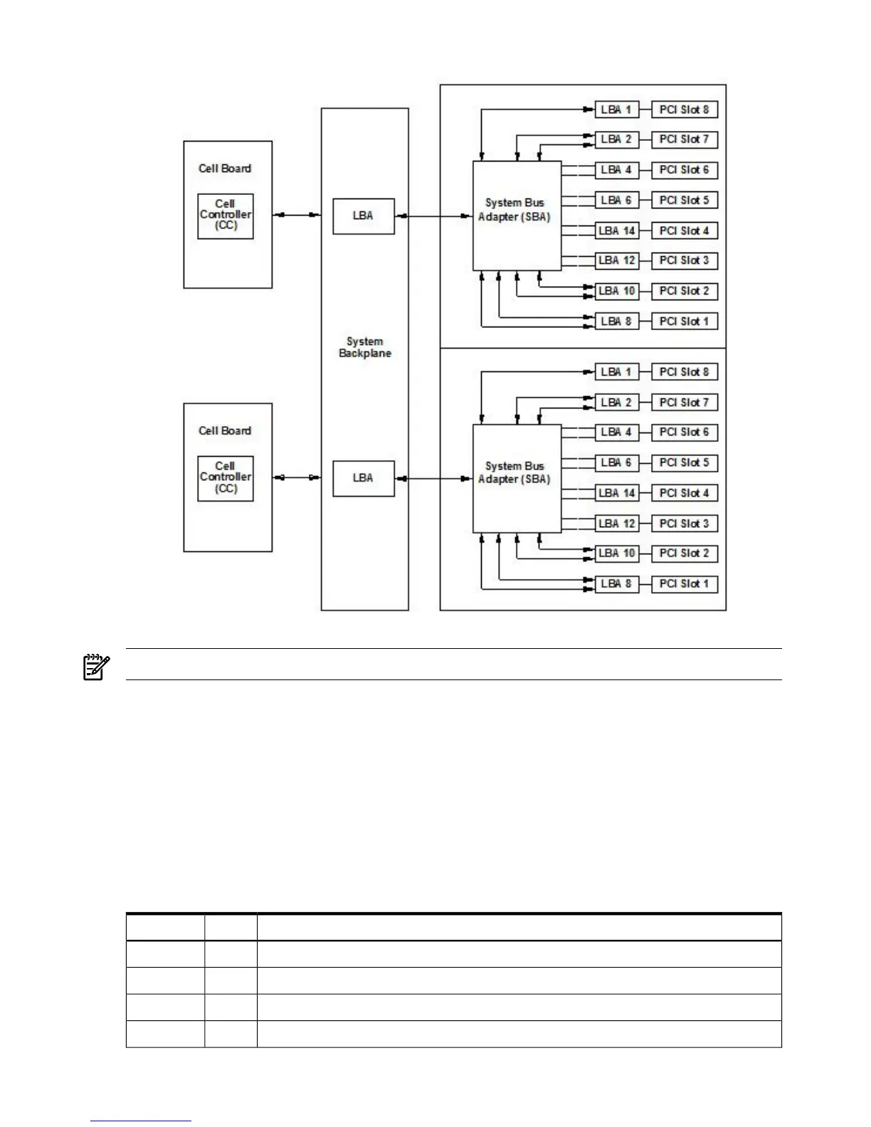
Figure 1-4 PCI-X Board to Cell Board Block Diagram
NOTE: PCI-X slots 1 through 7 are dual rope slots, while slot 8 is a single rope slot.
The PCI-X backplane is the primary I/O interface for HP 9000 rp7420 servers. It provides sixteen
64-bit, hot-plug PCI/PCI-X slots. Fourteen of the slots have dual ropes connected to the LBA
chips. The remaining two slots have a single rope connected to each LBA chip. Each of the sixteen
slots are capable of 66 MHz/33 MHz PCI or 133 MHz/66 MHz PCI-X. All sixteen PCI slots are
keyed for 3.3-volt connectors (accepting both Universal and 3.3-V cards). The PCI-X backplane
does not provide any 5-volt slots for the I/O cards. For more details, see Table 1-1.
The PCI-X backplane is physically one board but behaves like two independent partitions. SBA
0 and its associated LBAs and eight PCI-X slots form one I/0 partition. SBA 1 and its associated
LBAs and eight PCI-X slots form the other I/0 partition. One I/O partition can be powered down
separate from the other I/O partition.
Table 1-1 PCI-X Slot Types
Device
1
SlotI/O Partition
PCI (33 or 66 MHz) / PCI-X (66 or 133 MHz) 64-bit, 3.3V connector, hot plug slot80
PCI (33 or 66 MHz) / PCI-X (66 or 133 MHz) 64-bit, 3.3V connector, hot plug slot70
PCI (33 or 66 MHz) / PCI-X (66 or 133 MHz) 64-bit, 3.3V connector, hot plug slot60
PCI (33 or 66 MHz) / PCI-X (66 or 133 MHz) 64-bit, 3.3V connector, hot plug slot50
20 Overview
 Loading...


