List of Figures
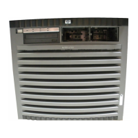
1-1 HP 9000 rp7420 server (front view)...............................................................................................17
1-2 HP 9000 rp7420 server (without front bezel)................................................................................18
1-3 System Backplane Block Diagram.................................................................................................19
1-4 PCI-X Board to Cell Board Block Diagram....................................................................................20
1-5 HP 9000 rp7420 server 8-Socket Block Diagram...........................................................................21
1-6 Cell Board......................................................................................................................................22
1-7 Memory Subsystem.......................................................................................................................23
1-8 CPU Locations on Cell Board........................................................................................................24
1-9 DIMM Slot Layout.........................................................................................................................26
1-10 Internal Disks................................................................................................................................27
1-11 Right-Front View of HP 9000 rp7420 server..................................................................................29
1-12 Left-Rear View of HP 9000 rp7420 server.....................................................................................30
2-1 Removing the Polystraps and Cardboard.....................................................................................32
2-2 Removing the Shipping Bolts and Plastic Cover...........................................................................33
2-3 Preparing to Roll Off the Pallet.....................................................................................................33
2-4 Securing the Cabinet......................................................................................................................34
2-5 RONI Lifter....................................................................................................................................35
2-6 Server with Shipping Box Removed.............................................................................................36
2-7 Remove Cushions for Lift Access..................................................................................................36
2-8 Raising a Server Off the Pallet.......................................................................................................37
2-9 Positioning the Lift Handles..........................................................................................................38
2-10 Inserting the Pins Into the Rack....................................................................................................38
2-11 Lift Handles Mounted...................................................................................................................39
3-1 Component Locations ...................................................................................................................42
3-2 Left Foam Block Position...............................................................................................................42
3-3 Right Foam Block Position............................................................................................................43
3-4 Foam Block Removal.....................................................................................................................43
3-5 Attaching a Caster to the Server....................................................................................................44
3-6 Securing Each Caster Cover to the Server.....................................................................................45
3-7 Server With Wheel Kit Installed....................................................................................................45
3-8 PCI I/O Slot Details........................................................................................................................48
4-1 Power Cord Configuration............................................................................................................51
4-2 Power Source versus Power Distribution......................................................................................52
4-3 Voltage Reference Points for IEC 320 C19 Plug.............................................................................53
4-4 Safety Ground Reference Check....................................................................................................54
4-5 Wall Receptacle Pinouts................................................................................................................55
4-6 Front Panel Display ......................................................................................................................57
4-7 MP Main Menu..............................................................................................................................58
4-8 The lc Command Screen..............................................................................................................59
4-9 The ls Command Screen................................................................................................................60
4-10 sa Command Screen......................................................................................................................61
4-11 Browser Window...........................................................................................................................61
4-12 The du Command Screen..............................................................................................................62
5-1 de Command Output....................................................................................................................69
5-2 Front Panel with LED Indicators...................................................................................................69
5-3 BPS LED Locations........................................................................................................................70
5-4 PCI Power Supply LED Locations.................................................................................................71
5-5 Front, Rear and PCI I/O Fan LEDs................................................................................................72
5-6 Cell Board LED Locations.............................................................................................................73
5-7 PCI OL* LED Locations.................................................................................................................74
5-8 Core I/O Card Bulkhead LEDs......................................................................................................75
9