Inspecting Optical Fiber Connectors
The Ethernet port rate is increasing and the quality requirement for optical bers
and optical cables is higher. Table 3-87 describes requirements for the loss of
optical ber connectors according to the national standard (GBT50312-2016).
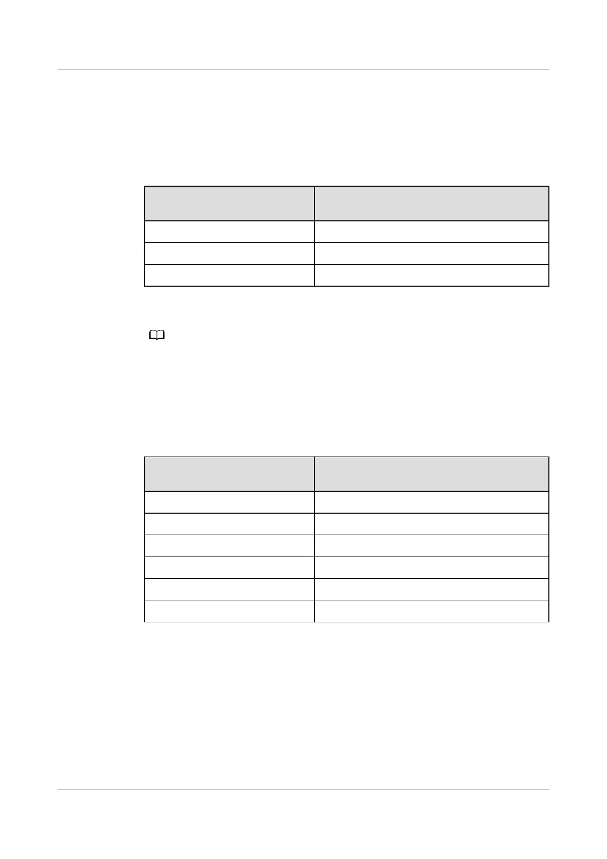
Table 3-87 Maximum attenuation of the optical
ber connector
Type Maximum attenuation of an optical ber
connector (dB)
Fiber splicing connector 0.3
Optical mechanical connector 0.3
Optical connector 0.75
Fiber cores are connected through connectors, such as the ODF, optical attenuator, and
ange, in splicing and mechanical modes.
Table 3-88 describes requirements for the reection of the optical ber connector
when Ethernet ports (such as 200G and 50G) use PAM4 encoding to double the
rate. More connectors bring lower requirements for the
reection.
Table 3-88 Maximum reection of connectors
Number of Optical Fiber
Connectors
Maximum Reection of Each Connector
(dB)
1 -22
2 -29
4 -33
6 -35
8 -37
10 -39
Link splice loss and
reectance values of the test methods and the following
processing steps:
1. After the optical ber at the peer end is disconnected, use the OTDR meter to
test the local end. Check whether the loss and reection of each link and
node are normal. (The loss of a
ber splicing connector should be less than
0.3 dB, the loss of a connector should be less than 0.75 dB, and the reection
of a connector should be less than -30 dB.) If the test result is not within the
required range, process the abnormal port.
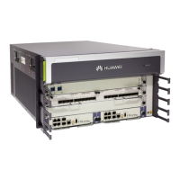
HUAWEI NetEngine 8000 F
Hardware Guide 3 Hardware Description
Issue 05 (2023-03-31) Copyright © Huawei Technologies Co., Ltd. 113
 Loading...