2. Locate the equipment room where the port resides based on the distance
between abnormal points in the OTDR test result. Preliminarily determine the
port location, disconnect the port, and perform an OTDR test on the port that
reports alarms. Check whether the distance is consistent with that in the
previous test. If not, continue to test other ports.
3. After the abnormal port is found, test the port using a ber microscope. If the
port is dirty, clean it.
4. After the port is cleaned, restore the port, and ensure that the connector is
tightened. Perform an OTDR test on the port to check whether loss and
reection of each link and node are normal.
5. If the fault persists, replace the ange and perform an OTDR test on the port
that reports alarms to check whether loss and
reection of each link and
node are normal.
6. If the fault persists, replace the optical ber and perform an OTDR test on the
port that reports alarms to check whether loss and
reection of each link and
node are normal.
7. If multiple abnormal points exist on the link, repeat steps 2 to 6.
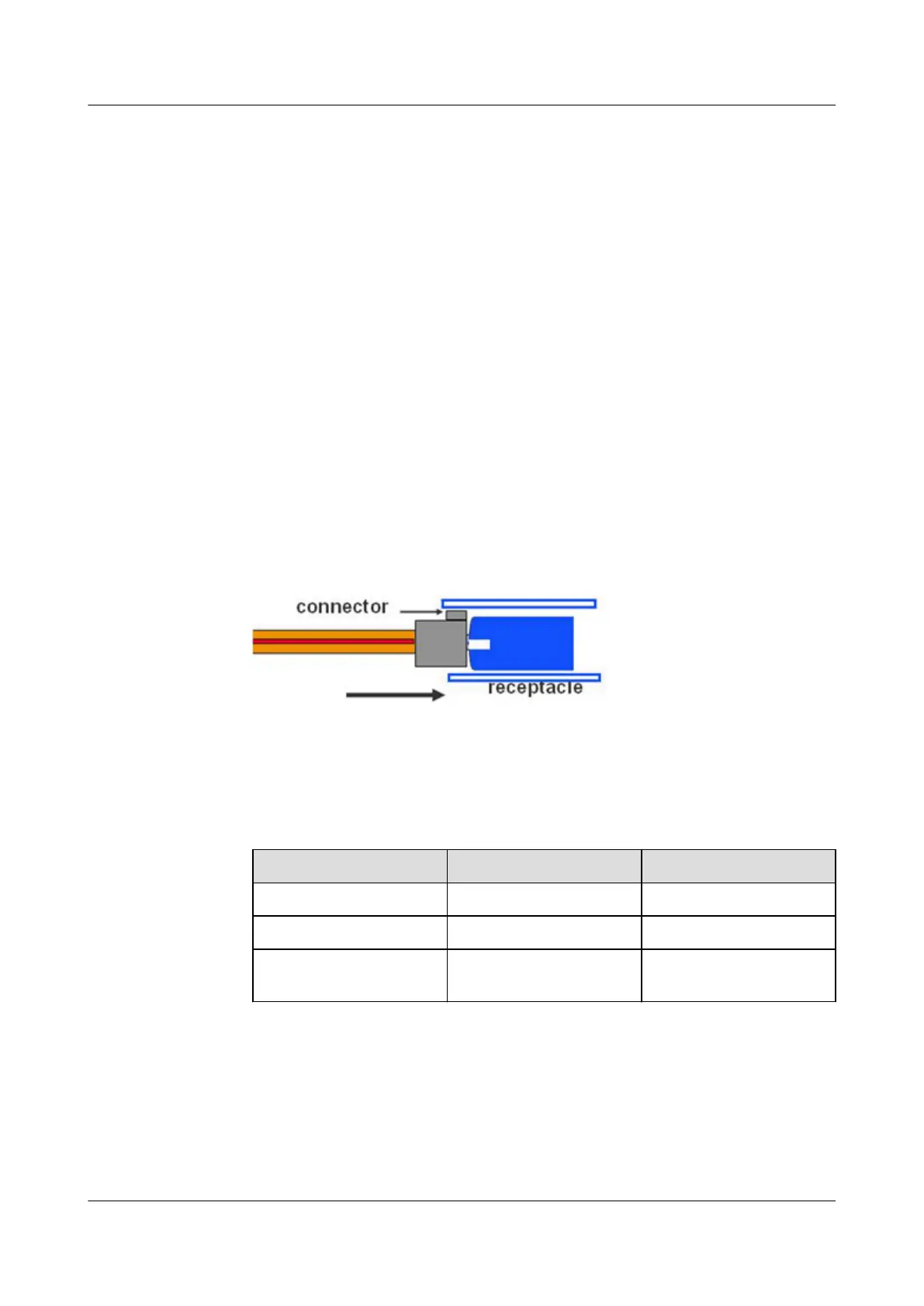
Other precautions
● The optical connector should be horizontally inserted in the receptacle to
avoid damages to the receptacle.
● Mixed use of multi-mode and single-mode optical bers is prohibited.
Otherwise, faults such as signal loss may occur.
Method of distinguishing optical modules in single mode and multi-mode.
Table 3-89 Method of distinguishing optical modules in single mode and
multi-mode
Item
Single mode Multi-mode
Transmission distance 10 km or longer Below 0.5 km
Wavelength Non-850 nm 850 nm
Information on the
label
SM MM
50G Optical Module Installation Guide
1. Precautions for optical module installation
(1) If a cabinet with a door is used, a sucient distance must be reserved between
the optical module and the cabinet door to prevent the puller or patch cord from
bumping on the door.
HUAWEI NetEngine 8000 F
Hardware Guide 3 Hardware Description
Issue 05 (2023-03-31) Copyright © Huawei Technologies Co., Ltd. 114
 Loading...