Operation Manual – QoS
Quidway S3100 Series Ethernet Switches Chapter 1
QoS Configuration
Huawei Technologies Proprietary
1-19
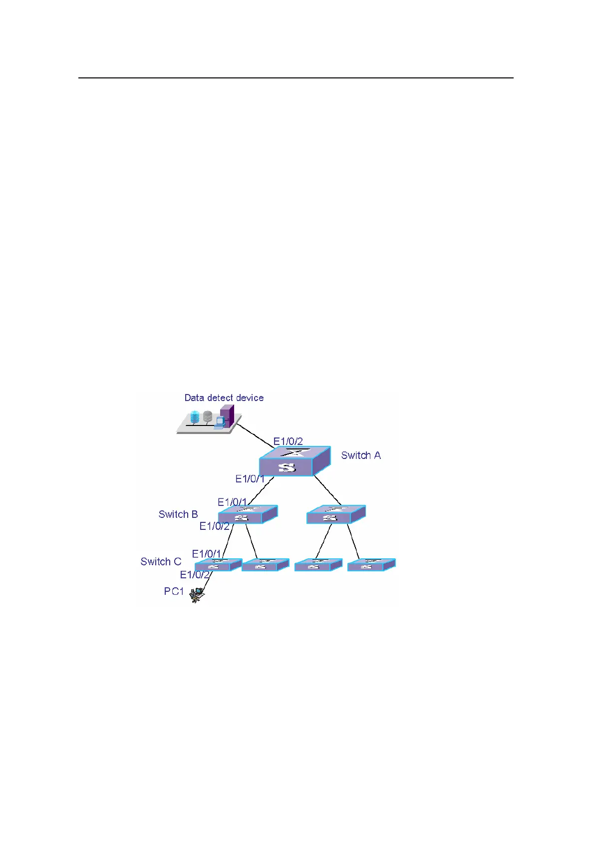
z Trunk port Ethernet1/0/1 of switch A is connected to Trunk port Ethernet 1/0/1 of
switch B.
z Trunk port Ethernet1/0/2 of switch B is connected to Trunk port Ethernet 1/0/1 of
switch C.
z Switch C connects to PC1 through Ethernet1/0/2.
The goal is to monitor and analyze outbound packets from PC1 using data detect
device.
To reach the goal with the help of RSPAN, configure as follows:
z Define VLAN10 as the remote-probe VLAN.
z Switch A acts as the destination switch. Ethernet1/0/2, which is connected to the
data detect device, acts as the destination monitoring port. Do not enable STP on
Ethernet1/0/2.
z Switch B acts as the intermediate switch.
z Switch C acts as the source switch. Specify Ethernet1/0/2 as the source
monitoring port, Ethernet1/0/5 as the reflector port and Ethernet1/0/5 as the
Access port. Do not enable STP on Ethernet1/0/5.
II. Network Diagram
Figure 1-5 Network diagram for RSPAN
III. Configuration procedure
# Configurations on switch C.
<Quidway> system-view
[Quidway] vlan 10
[Quidway-vlan10] remote-probe vlan enable
[Quidway-vlan10] quit
 Loading...