EasyManuals Logo

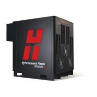
Hypertherm HyPerformance Plasma HPR400 User Manual

Hypertherm HyPerformance Plasma HPR400
355 pages
To Next Page IconTo Next Page
To Previous Page IconTo Previous Page
Page #286 background imageLoading...
Page #286 background image
Wiring Diagrams
HPR400XD Auto Gas 806160 7-3
Switch, Level,
Normally Closed
Time Delay Closed,
NO/Off
Transformer
Electrode
Torch Symbols
Nozzle
Shield
Torch
Transformer, Air Core
Transformer Coil
Valve, Solenoid
Voltage Source
Zener Diode
VAC Source
Triac
Switch, Pressure,
Normally Closed
Switch, Pressure,
Normally Open
Switch, 1 Pole, 1 Throw
Switch, 1 Pole, 2 Throw
Switch, 1 Pole, 1 Throw,
Center Off
Switch, Temperature,
Normally Closed
Switch, Temperature,
Normally Open
Time Delay Closed,
NC/Off
Time Delay Open,
NO/Off
Time Delay Open,
NC/On
Terminal Block
Torch, HyDefinition™
Switch, Flow

Table of Contents

Questions and Answers:

Question and Answer IconNeed help?

Do you have a question about the Hypertherm HyPerformance Plasma HPR400 and is the answer not in the manual?

Hypertherm HyPerformance Plasma HPR400 Specifications

General IconGeneral
Duty Cycle100% at 400 A
Cutting Capacityup to 50 mm (2 in)
Output Current30-400 A
Input Voltage200 – 480 V, 3-PH, 50/60 Hz
Gas SupplyOxygen, Air, Nitrogen

Related product manuals