5.1 External Dimensions
5-2
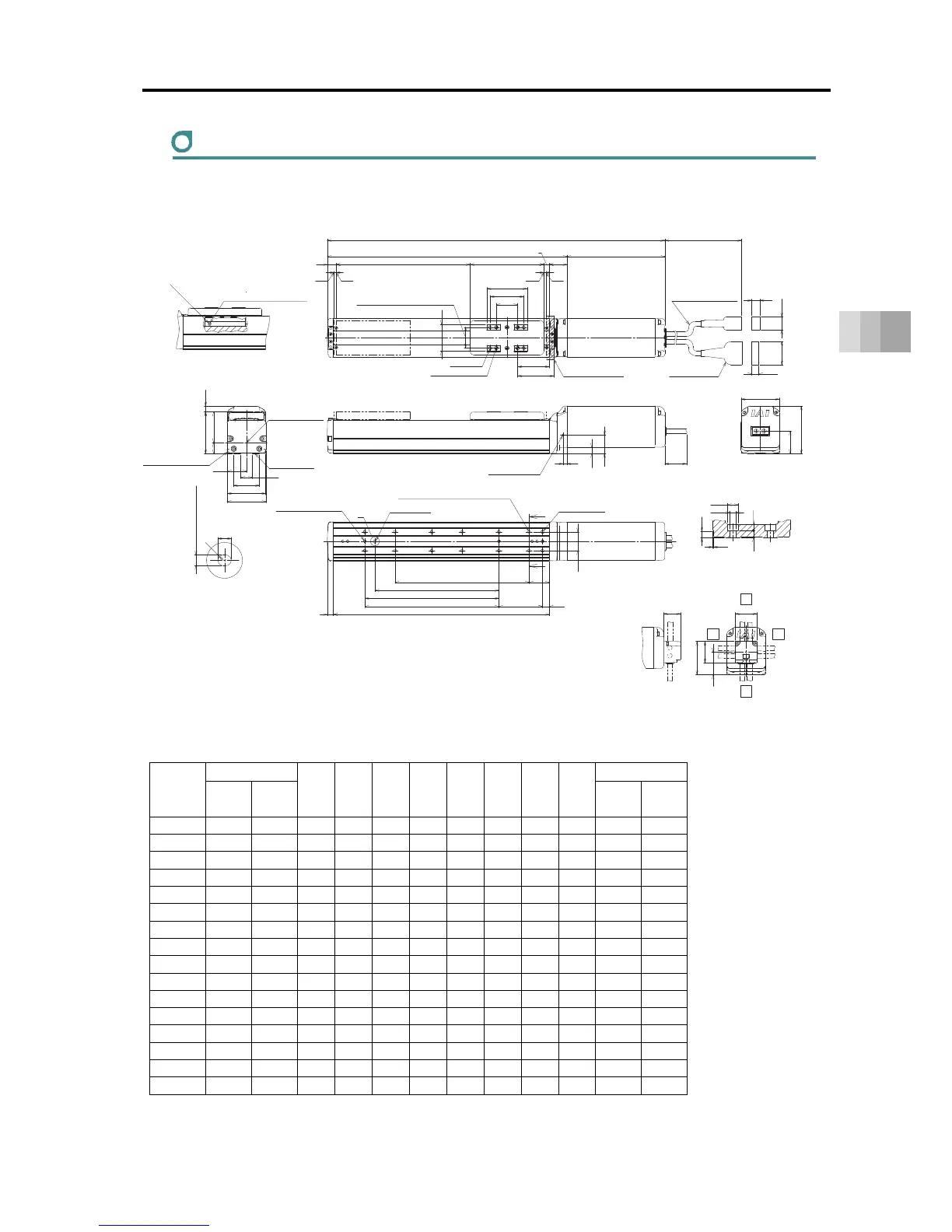
5. External Dimensions
RCS4-SA6C
ST: Stroke, M.E.: Mechanical End, S.E.: Stroke End
■ Dimensions and Mass by Stroke
Unit: mm
Stroke
L
A B D E G H J K
Mass [kg]
W/o
Brake
With
Brake
W/o
Brake
With
Brake
50 353.5 389.5 207.5 172 0 4 1 4 0 0 2.0 2.3
100 403.5 439.5 257.5 222 1 6 1 4 85 100 2.2 2.5
150 453.5 489.5 307.5 272 1 6 2 6 85 100 2.4 2.7
200 503.5 539.5 357.5 322 2 8 2 6 185 200 2.6 2.9
250 553.5 589.5 407.5 372 2 8 3 8 185 200 2.7 3.0
300 603.5 639.5 457.5 422 3 10 3 8 285 300 2.9 3.2
350 653.5 689.5 507.5 472 3 10 4 10 285 300 3.1 3.4
400 703.5 739.5 557.5 522 4 12 4 10 385 400 3.3 3.6
450 753.5 789.5 607.5 572 4 12 5 12 385 400 3.4 3.7
500 803.5 839.5 657.5 622 5 14 5 12 485 500 3.6 3.9
550 853.5 889.5 707.5 672 5 14 6 14 485 500 3.8 4.1
600 903.5 939.5 757.5 722 6 16 6 14 585 600 4.0 4.3
650 953.5 989.5 807.5 772 6 16 7 16 585 600 4.2 4.5
700 1003.5 1039.5 857.5 822 7 18 7 16 685 700 4.3 4.6
750 1053.5 1089.5 907.5 872 7 18 8 18 685 700 4.5 4.8
800 1103.5 1139.5 957.5 922 8 20 8 18 785 800 4.7 5.0
(54)
ST
13
3 3
(12)
(19.5)
(34.5)
(10.5)
(300)
16.5
46
25
Section Z-Z
Detail of Counterbore for Base Attachment
(R)
5
CJRCJL
CJT
CJB
32
50
34
32
M.E. S.E. M.E.
↓V
Actuator Cable
Allowable Bending Radius R50
40
4-φ5H7 Reamed Depth 6
26.5
A
4-M5 Depth 10
60
50
±0.02
110
L
32
8
47
17.5
58
62.5
38.5
57
(8.5)
28.5
Oblong hole
(Not for Strokes 50)
P
65
9
30
B
28
10
Z
Z
(34)
71
57
28
9.5
6
Nipple Diameter
φ3.5
Ball screw For guides
Grease Nipple (the other side the same)
Grease oil supply port
Arrow view V
31 (Tolerance ±0.02 between the reamed hole)
Home
182 (With Brake)
146 (W/o Brake)
Be cautious for interference.
Slider Installed Load
Cable joint Connector
Upper Surface of Slider
Allowable Moment
Reference position for Offset
Base seating surface
Reference surface
(Range of Dimension B)
M3 Depth 6
(For ground connection,
the other side the same)
Maintain it
more than 100
4
+
0.012
0
From Base seating surface Depth 5.5
Detailed View P
Details Base oblong hole
3-φ4H7 Reamed Depth 5.5
(From Base seating surface)
(Number of the reamer holes 2
at the time of 50st)
Through H-φ4.5, Depth φ8, Counter Boring Depth 4.5
(From back side)
G×100P
K (φ4 hole - φ4 hole)
D×100P
J (φ4 hole - oblong hole)
Through E-M5
(Screwing Depth 10)
φ8
φ4.5
4.9
4.5
5.5
(0.5)
Cable Exit Direction (Optional)
Right
Left
Top
Bottom
 Loading...


