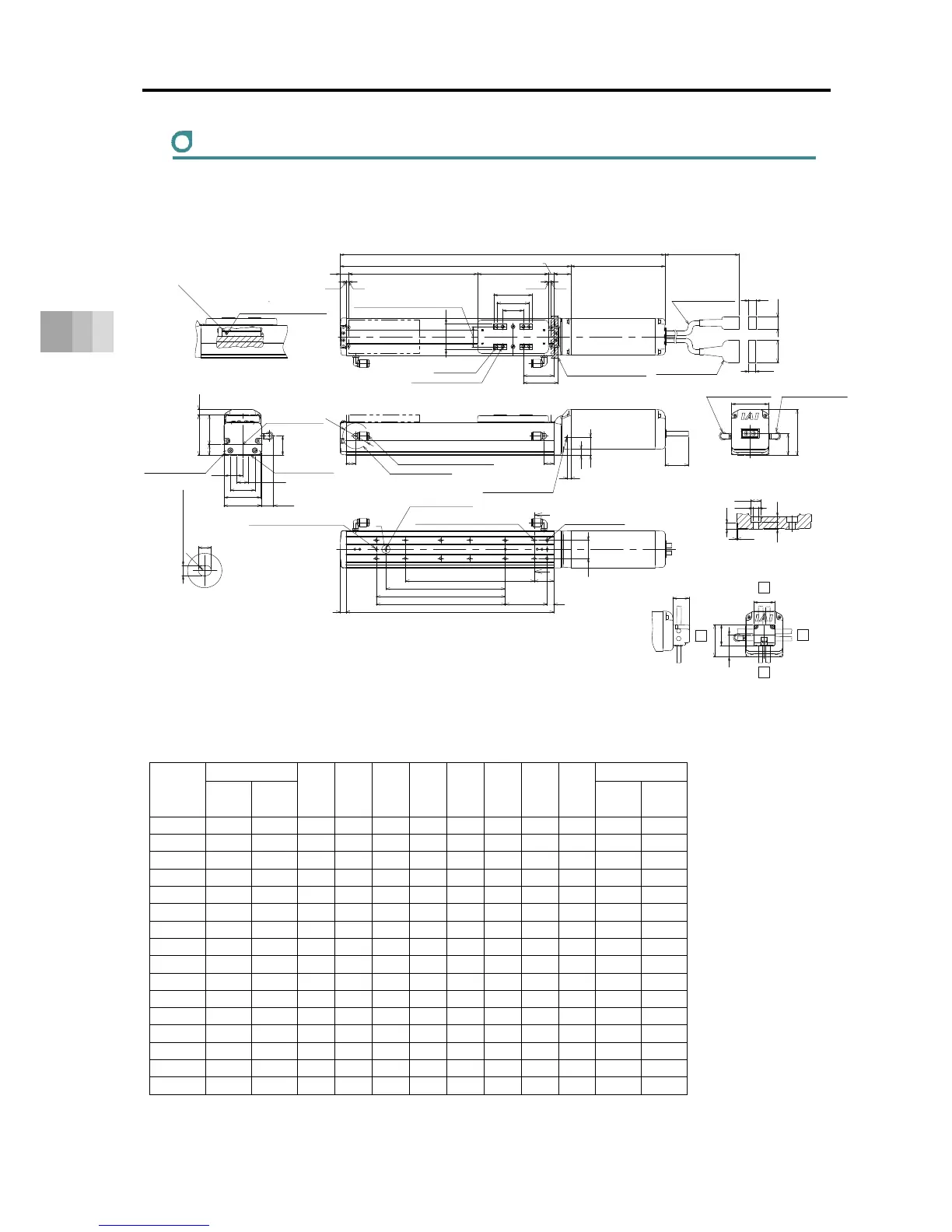
5.1 External Dimensions
5-13
5. External Dimensions
RCS4CR-SA6C
ST: Stroke, M.E.: Mechanical End, S.E.: Stroke End
■ Dimensions and Mass by Stroke
Unit: mm
Stroke
L
A B D E G H J K
Mass [kg]
W/o
Brake
With
Brake
W/o
Brake
With
Brake
50 353.5 389.5 207.5 172 0 4 1 4 0 0 2.0 2.3
100 403.5 439.5 257.5 222 1 6 1 4 85 100 2.2 2.5
150 453.5 489.5 307.5 272 1 6 2 6 85 100 2.4 2.7
200 503.5 539.5 357.5 322 2 8 2 6 185 200 2.6 2.9
250 553.5 589.5 407.5 372 2 8 3 8 185 200 2.7 3.0
300 603.5 639.5 457.5 422 3 10 3 8 285 300 2.9 3.2
350 653.5 689.5 507.5 472 3 10 4 10 285 300 3.1 3.4
400 703.5 739.5 557.5 522 4 12 4 10 385 400 3.3 3.6
450 753.5 789.5 607.5 572 4 12 5 12 385 400 3.4 3.7
500 803.5 839.5 657.5 622 5 14 5 12 485 500 3.6 3.9
550 853.5 889.5 707.5 672 5 14 6 14 485 500 3.8 4.1
600 903.5 939.5 757.5 722 6 16 6 14 585 600 4.0 4.3
650 953.5 989.5 807.5 772 6 16 7 16 585 600 4.2 4.5
700 1003.5 1039.5 857.5 822 7 18 7 16 685 700 4.3 4.6
750 1053.5 1089.5 907.5 872 7 18 8 18 685 700 4.5 4.8
800 1103.5 1139.5 957.5 922 8 20 8 18 785 800 4.7 5.0
Grease oil supply port
Arrow view V
Nipple Diameter
φ3.5
Ball screw For guides
Grease Nipple (the other side the same)
* No pipe joint for slider roller type (SR)
(φ40)
9.5
28
6
15 15
Outer Diameter of Applied Tube:φ6
Rotation Area of Joint
(54)
ST13
3 3
(12)
(19.5)
(34.5)
(10.5)
(300)
60
50
40
32
±0.02
L
A
110
8
26.5
(47)
M.E. S.E. M.E.
Actuator Cable
Allowable Bending Radius R50
↓V
B9
28
1065
30
(34)
71
57
Joint Attached Position
Standard Side
Joint Attached Position
Opposite Side (Option)
16.5
46
62.5
17.5
38.5
57
58
(8.5)
30
(18.9)
28.5
(R)
5
34
32
50
32
25
Section Z-Z
Detail of Counterbore for Base Attachment
Z
Z
P
182 (With Brake)
146 (W/o Brake)
31
(Tolerance
±0.02
between the reamed hole)
Home
4-φ5H7 Reamed Depth 6
4-M5 Depth 10
Be cautious for interference.
Slider Installed Load
Cable joint Connector
Allowable Moment
Reference position for Offset
Base seating surface
Upper Surface of Slider
Reference surface
(Range of Dimension B)
M3 Depth 6
(For ground connection,
the other side the same)
Maintain it
more than 100
Detailed View P
Details Base oblong hole
4
+
0.012
0
From Base seating surface Depth 5.5
3-φ4H7 Reamed Depth 5.5
(From Base seating surface)
(Number of the reamer holes 2
at the time of 50st)
Oblong hole
(Not for Strokes 50)
Through H-φ4.5, Depth φ8, Counter Boring Depth 4.5
(From back side)
Through E-M5
(Screwing Depth 10)
K (φ4 hole - φ4 hole)
G×100P
D×100P
J (φ4 hole - oblong hole)
φ4.5
5.5
4.9
φ8
4.5
(0.5)
Cable Exit Direction (Optional)
Right
Left
CJL
CJT
Top
CJR
CJB
Bottom
 Loading...


