5.1 External Dimensions
5-12
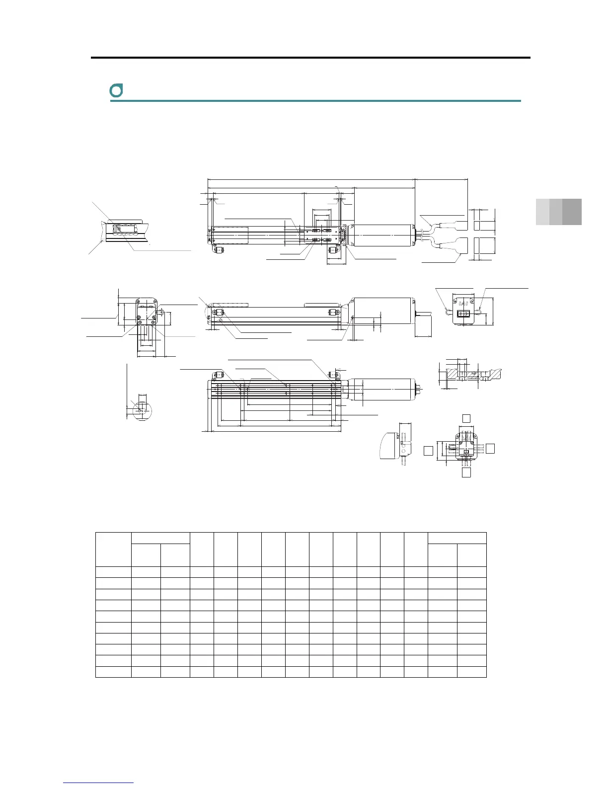
5. External Dimensions
RCS4CR-SA4C
ST: Stroke, M.E.: Mechanical End, S.E.: Stroke End
■ Dimensions and Mass by Stroke
Unit: mm
Stroke
L
A B C D E F G H J K
Mass [kg]
W/o
Brake
With
Brake
W/o
Brake
With
Brake
50 305 341 172 134 50 - 6 50 0 8 35 50 1.2 1.4
100 355 391 222 184 50 1 6 100 0 8 85 100 1.3 1.5
150 405 441 272 234 100 1 6 50 1 10 85 100 1.4 1.6
200 455 491 322 284 50 2 8 100 1 10 185 200 1.5 1.7
250 505 541 372 334 100 2 8 50 2 12 185 200 1.5 1.7
300 555 591 422 384 50 3 10 100 2 12 285 300 1.6 1.8
350 605 641 472 434 100 3 10 50 3 14 285 300 1.7 1.9
400 655 691 522 484 50 4 12 100 3 14 385 400 1.8 2.0
450 705 741 572 534 100 4 12 50 4 16 385 400 1.9 2.1
500 755 791 622 584 50 5 14 100 4 16 485 500 2.0 2.2
(41)
(12)
(19.5)
(34.5)
(10.5)
(300)
ST12
3 3
(
φ
40)
12
(36)
25
Section Z-Z
Detail of Counterbore for Base Attachment
(R)
4
↓V
S.E.
Actuator Cable
Allowable Bending Radius R50
M.E. M.E.
L
A
76 30
40
32
24
25
4
30
* No pipe joint for slider roller type (SR)
Joint Attached Position
Opposite Side (Option)
Joint Attached Position
Standard Side
60
(25)
47
Outer Diameter of Applied Tube:φ6
Rotation Area of Joint
17
3
6
3.5
6
32
41
25
32
P
17
B
12
20
C
8
50 F
Z
Z
40
28
48
39
25
(12)
10
(18.9)
19.5
Grease oil supply port
Arrow view V
φ8
Nipple Diameter
φ3.5
Openings
Ball screw For guides
Grease Nipple (the other side the same)
±0.02
Home
169 (With Brake)
133 (W/o Brake)
20 (Tolerance ±0.02 between the reamed hole)
4-φ3H7 Reamed Depth 6
4-M3 Depth 7
Be cautious for interference.
Slider Installed Load
Cable joint Connector
Allowable Moment
Reference position for Offset
Reference surface
(Range of Dimension B)
Base seating surface
Upper Surface of Slider
M3 Depth 6
(For ground connection,
the other side the same)
Maintain it
more than 100
Detailed View P
Details Base oblong hole
3
+
0.010
0
From Base seating surface Depth 4
oblong hole
Through E-M4
(Screwing Depth 6)
Through H-φ3.4, Depth φ6.5, Counter Boring Depth 3.5
(From back side)
2-φ3H7 Reamed Depth 4
(From Base seating surface)
50 (25 at the time of 50st)
K (φ3 hole - φ3 hole)
G×100P
D×100P (50 at the time of 50st)
J (φ3 hole - oblong hole)
φ3.4
2.5
6.1
φ6.5
3.5
(0.5)
Cable Exit Direction (Optional)
Right
Left
CJL
CJT
Top
CJR
CJB
Bottom
 Loading...


