5.1 External Dimensions
5-7
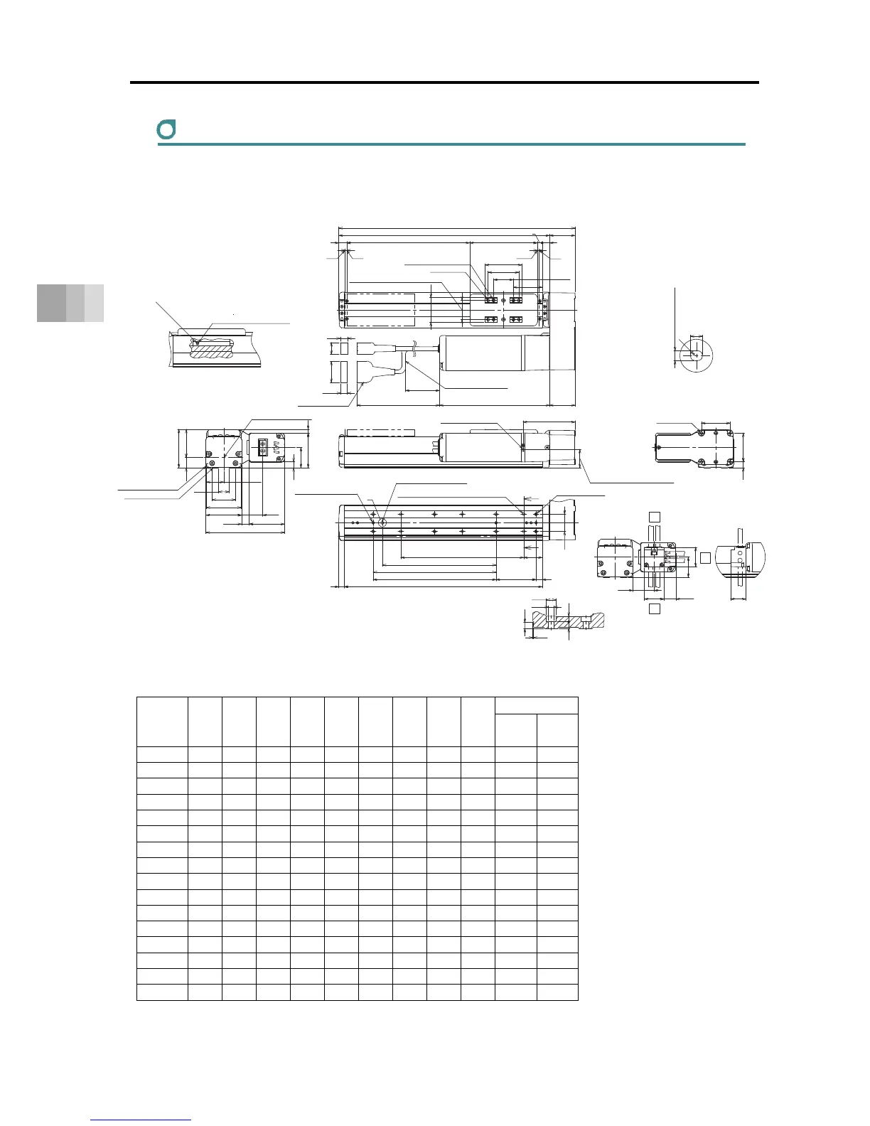
5. External Dimensions
RCS4-SA6R
ST: Stroke, M.E.: Mechanical End, S.E.: Stroke End
■ Dimensions and Mass by Stroke
Unit: mm
Stroke L A B D E G H J K
Mass [kg]
W/o
Brake
With
Brake
50 234.5 193 172 0 4 1 4 0 0 2.4 2.7
100 284.5 243 222 1 6 1 4 85 100 2.5 2.8
150 334.5 293 272 1 6 2 6 85 100 2.7 3.0
200 384.5 343 322 2 8 2 6 185 200 2.9 3.2
250 434.5 393 372 2 8 3 8 185 200 3.1 3.4
300 484.5 443 422 3 10 3 8 285 300 3.2 3.5
350 534.5 493 472 3 10 4 10 285 300 3.4 3.7
400 584.5 543 522 4 12 4 10 385 400 3.6 3.9
450 634.5 593 572 4 12 5 12 385 400 3.8 4.1
500 684.5 643 622 5 14 5 12 485 500 4.0 4.3
550 734.5 693 672 5 14 6 14 485 500 4.1 4.4
600 784.5 743 722 6 16 6 14 585 600 4.3 4.6
650 834.5 793 772 6 16 7 16 585 600 4.5 4.8
700 884.5 843 822 7 18 7 16 685 700 4.7 5.0
750 934.5 893 872 7 18 8 18 685 700 4.9 5.2
800 984.5 943 922 8 20 8 18 785 800 5.0 5.3
(10.5)
ST
13
3 3
(12)
(19.5)
(34.5)
(300)
16.5
46
84.5
M.E.
S.E.
Actuator Cable
Allowable Bending Radius R50
M.E.
41.5
60
50
40
32
±0.02
110
(41.5)
L
A
8
12
47
↓V
(R)
5
17.5
34.3
58
57.5
56.5
33
128
38.5
9.5
57
62.5
(6)
(12.5)
28.5
47
479.5
P
10
28
B
65
9
30
Z
Z
32
33
34.5
(19.5)
32
25
Section Z-Z
Detail of Counterbore for Base Attachment
Grease oil supply port
Arrow view V
Nipple Diameter
φ3.5
Ball screw For guides
Grease Nipple (the other side the same)
Home
4-φ5H7H7 Reamed Depth 6
4-M5 Depth 10
31 (Tolerance ±0.02 between the reamed hole)
Cable joint Connector
Maintain it
more than 100
215 (With Brake)
179 (W/o Brake)
Detailed View P
Details Base oblong hole
4
+
0.012
0
From Base seating surface Depth 5.5
Allowable Moment
Reference position for Offset
Upper Surface of Slider
Reference surface
(Range of Dimension B)
Base seating surface
M3 Depth 6
(For ground connection)
30
(at the time of ML side-mounted direction)
36
(at the time of MR side-mounted direction)
4-M5 Depth 10
3-φ4H7 Reamed Depth 5.5
(From Base seating surface)
(Number of the reamer holes 2
at the time of 50st)
Oblong hole
(Not for Strokes 50)
Through H-φ4.5, Depth φ8, Counter Boring Depth 4.5
(From back side)
Through E-M5
(Screwing Depth 10)
D×100P
G×100P
K (φ4 hole - φ4 hole)
J (φ4 hole - oblong hole)
Cable Exit Direction (Optional)
4.9
φ8
(0.5)
φ4.5
4.55.5
CJT
CJO
CJB
Top
Bottom
Outward
 Loading...


