5.1 External Dimensions
5-8
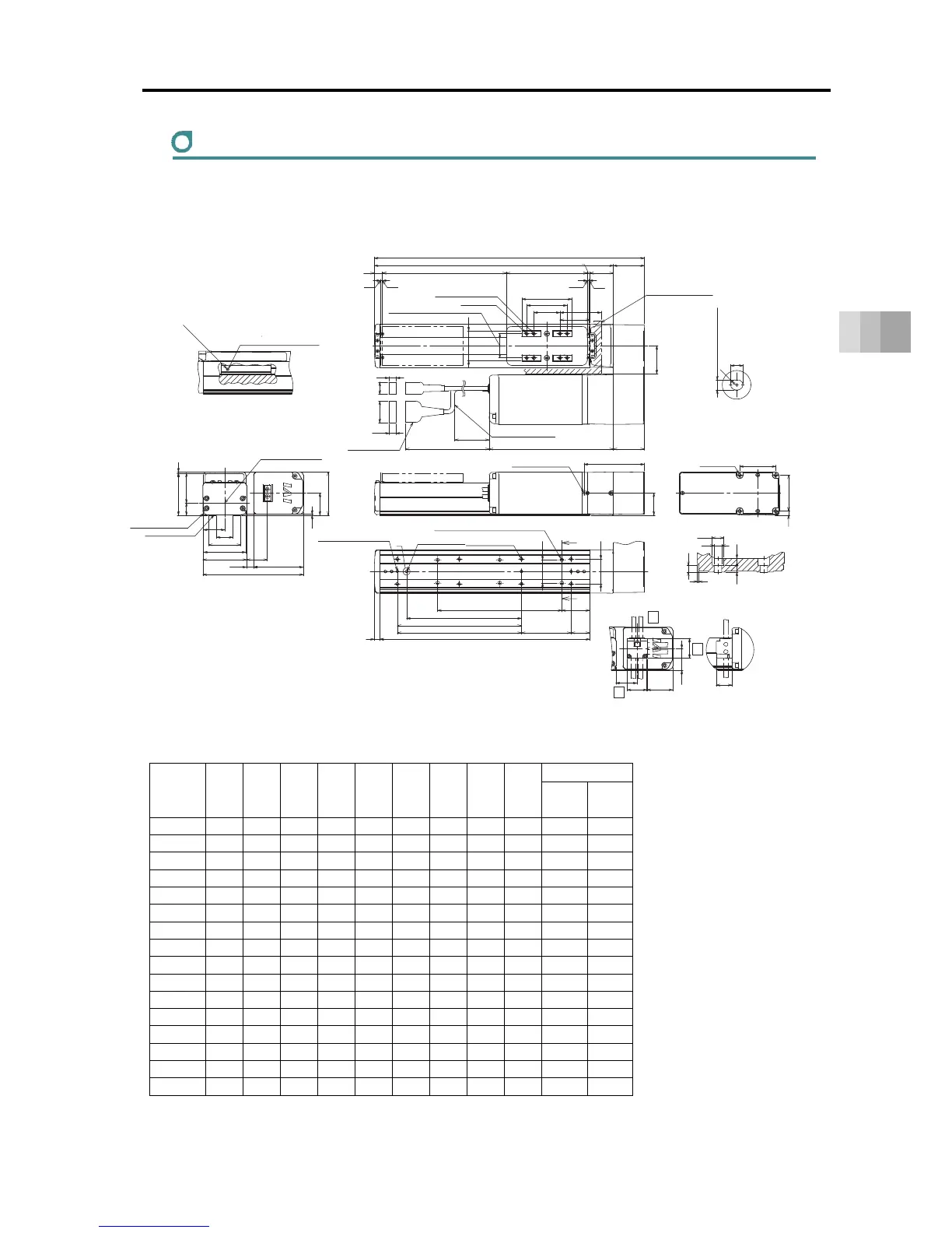
5. External Dimensions
RCS4-SA7R
ST: Stroke, M.E.: Mechanical End, S.E.: Stroke End
■ Dimensions and Mass by Stroke
Unit: mm
Stroke L A B D E G H J K
Mass [kg]
W/o
Brake
With
Brake
50 285 235 188 0 4 1 4 0 0 4.3 4.8
100 335 285 238 1 6 1 4 85 0 4.6 5.1
150 385 335 288 1 6 2 6 85 100 4.8 5.3
200 435 385 338 2 8 2 6 185 200 5.0 5.5
250 485 435 388 2 8 3 8 185 200 5.3 5.8
300 535 485 438 3 10 3 8 285 300 5.5 6.0
350 585 535 488 3 10 4 10 285 300 5.8 6.3
400 635 585 538 4 12 4 10 385 400 6.0 6.5
450 685 635 588 4 12 5 12 385 400 6.2 6.7
500 735 685 638 5 14 5 12 485 500 6.5 7.0
550 785 735 688 5 14 6 14 485 500 6.7 7.2
600 835 785 738 6 16 6 14 585 600 6.9 7.4
650 885 835 788 6 16 7 16 585 600 7.2 7.7
700 935 885 838 7 18 7 16 685 700 7.4 7.9
750 985 935 888 7 18 8 18 685 700 7.6 8.1
800 1035 985 938 8 20 8 18 785 800 7.9 8.4
19.5
48
(45)
ST
13
3
3
(66.5)
(12)
(19.5)
(34.5)
(10.5)
(300)
(R)
5
35.5
26.5
51.5
68
70
67.5
161.5
(2)
(34)
69.5
1.5
80
(11.5)
34
58
58
6.5
S.E.
M.E.
M.E.
↓V
Actuator Cable
Allowable Bending Radius R50
65
80
±0.02
42
48
(50)
L
50
A
130 38
4
48
97
35.5
P
B
3080
45
9
40
37
Z
Z
34
(41.5)
32
35.5
32
25
Section Z-Z
Detail of Counterbore for Base Attachment
Grease oil supply port
Arrow view V
Nipple Diameter
φ3.5
Ball screw For guides
Grease Nipple (the other side the same)
Home
Be cautious for interference.
Slider Installed Load
4-φ5H7 Reamed Depth 10
4-M5 Depth 10
39 (Tolerance ±0.02 between the reamed hole)
Detailed View P
Details Base oblong hole
4
+
0.012
0
From Base seating surface Depth 6
Cable joint Connector
Maintain it
more than 100
222 (With Brake)
200 (W/o Brake)
Allowable Moment
Reference position for Offset
Upper Surface of Slider
Reference surface
(Range of Dimension B)
Base seating surface
M3 Depth 6
(For ground connection)
4-M6 Depth 12
Oblong hole
(Not for Strokes 50)
Through H-φ6, Depth φ9.5, Counter Boring Depth 5.5
(From back side)
Through E-M5
(Screwing Depth 10)
3-φ4H7 Reamed Depth 6
(From Base seating surface)
(Number of the reamer holes 2
at the time of 50 and 100st)
D×100P
G×100P
K (φ4 hole - φ4 hole)
J (φ4 hole - oblong hole)
5.3
φ9.5
(1)
φ6
5.5
5.5
Cable Exit Direction (Optional)
CJT
CJO
CJB
Top
Bottom
Outward
 Loading...


