5.1 External Dimensions
5-10
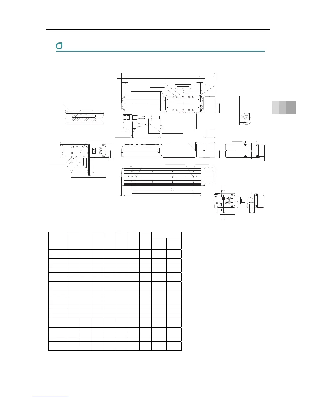
5. External Dimensions
RCS4-SA8R
ST: Stroke, M.E.: Mechanical End, S.E.: Stroke End
■ Dimensions and Mass by Stroke
Unit: mm
Stroke L A B D E J K
Mass [kg]
W/o
Brake
With
Brake
50 309 259 230 1 4 0 0 5.6 6.1
100 359 309 280 2 6 0 100 5.9 6.4
150 409 359 330 2 6 80 100 6.2 6.7
200 459 409 380 3 8 180 200 6.4 6.9
250 509 459 430 3 8 180 200 6.7 7.2
300 559 509 480 4 10 280 300 7.0 7.5
350 609 559 530 4 10 280 300 7.3 7.8
400 659 609 580 5 12 380 400 7.6 8.1
450 709 659 630 5 12 380 400 7.9 8.4
500 759 709 680 6 14 480 500 8.2 8.7
550 809 759 730 6 14 480 500 8.5 9.0
600 859 809 780 7 16 580 600 8.8 9.3
650 909 859 830 7 16 580 600 9.1 9.6
700 959 909 880 8 18 680 700 9.4 9.9
750 1009 959 930 8 18 680 700 9.6 10.1
800 1059 1009 980 9 20 780 800 9.9 10.4
850 1109 1059 1030 9 20 780 800 10.2 10.7
900 1159 1109 1080 10 22 880 900 10.5 11.0
950 1209 1159 1130 10 22 880 900 10.8 11.3
1000 1259 1209 1180 11 24 980 1000 11.1 11.6
1050 1309 1259 1230 11 24 980 1000 11.4 11.9
1100 1359 1309 1280 12 26 1080 1100 11.7 12.2
(93)
(45)
ST18.5
3
3
(12)
(19.5)
(34.5)
(300)
(10.5)
22
45.5
11
↓V
Actuator Cable
Allowable Bending Radius R50
M.E
S.E. M.E.
18
90
40
60
80
L
A
(50)
50
165
75
7.5
40
37
97
169
35
65
83
85
67.5
(1)
37
71
3
(4)
(26)
(3.5)
80
5.6
41.5
588
58
P
100
40
B
50
(R)
7
25
37
32
26.5
(41.5)
32
Nipple Diameter
φ3.5
Ball screw For guides
Grease Nipple (the other side the same)
Grease oil supply port
Arrow view V
Be cautious for interference.
Slider Installed Load
Home
2-φ6H7 Reamed Depth 10
Through 4-M8
(Screwing Depth 12)
63 (Tolerance ±0.02 between the reamed hole)
6
+
0.012
0
From Base seating surface Depth 6.5
Detailed View P
Details Base oblong hole
Maintain it
more than 100
257 (With Brake)
222 (W/o Brake)
Cable joint Connector
Allowable Moment
Reference position for Offset
Reference surface
(Range of Dimension B)
Base seating surface
Upper Surface of Slider
M3 Depth 6
(For ground connection)
4-M6 Depth 12
Oblong hole
(Not for Strokes 50 and 100)
3-φ6H7 Reamed Depth 6.5
(From Base seating surface)
(Number of the reamer holes 2
at the time of 50st)
Through E-M6
(Screwing Depth 12)
K (φ6 hole - φ6 hole)
D×100P
J (φ6 hole - oblong hole)
Cable Exit Direction (Optional)
CJT
CJB
Top
Bottom
CJO
Outward
 Loading...


