v PCI-riser connector 1: Carefully fit the two alignment slots on the side of the
assembly onto the two alignment brackets on the side of the chassis; align
the rear of the assembly with the guides on the rear of the server.
v PCI-riser connector 2: Carefully align the bottom edge (the contact edge) of
the riser-card assembly with the riser-card connector on the system board;
align the rear of the assembly with the guides on the rear of the server.
4. Press down on the assembly. Make sure that the riser-card assembly is fully
seated in the riser-card connector on the system board.
5. Perform any configuration tasks that are required for the adapter.
6. Install the server cover (see “Installing the cover” on page 206).
7. Slide the server into the rack.
8. Reconnect the external cables; then, reconnect the power cords and turn on the
peripheral devices and the server.
Removing the optional dual-port network adapter
To remove the network adapter, complete the following steps:
1. Read the safety information that begins on page vii and “Installation guidelines”
on page 191.
2. Turn off the server and peripheral devices and disconnect all power cords and
external cables.
3. Remove the cover (see “Removing the cover” on page 205).
4. Remove the PCI riser-card assembly 2 (see “Removing a PCI riser-card
assembly” on page 218).
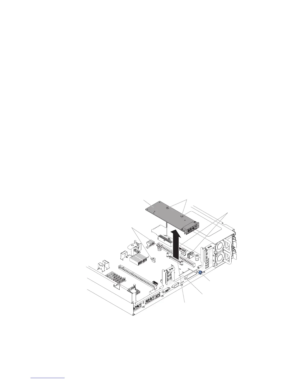
5. Loosen the thumbscrew on the rear of the chassis.
Pin
Thumbscrew
Screw holes
Retention
brackets
Network
adapter
Captive screws
Network
adapter connector
6. Grasp the network adapter and disengage it from the pin, standoffs, retention
brackets, and the connector on the system board; then, lift the adapter out of
the port openings on the rear of the chassis and remove it from the server.
224 IBM System x3650 M4 Type 7915: Problem Determination and Service Guide

 Loading...


