Table 15. Non-mirroring (normal) mode DIMM installation sequence
Number of installed
microprocessor DIMM connector population sequence
One microprocessor
installed
1, 4, 9, 12, 2, 5, 8, 11, 3, 6, 7, 10
Two microprocessors
installed
1, 13, 4, 16, 9, 21, 12, 24, 2, 14, 5, 17, 8, 20, 11, 23, 3, 15,
6, 18, 7, 19, 10, 22
Memory mirrored channel
Memory mirrored channel mode replicates and stores data on two pairs of DIMMs
within two channels simultaneously. If a failure occurs, the memory controller
switches from the primary pair of memory DIMMs to the backup pair of DIMMs. To
enable memory mirrored channel through the Setup utility, select System Settings
→ Memory. For more information, see “Using the Setup utility” on page 301. When
you use the memory mirrored channel feature, consider the following information:
v When you use memory mirrored channel, you must install a pair of DIMMs at a
time. The two DIMMs in each pair must be identical in size, type, and rank
(single, dual, or quad), and organization, but not in speed. The channels run at
the speed of the slowest DIMM in any of the channels.
v The maximum available memory is reduced to half of the installed memory when
memory mirrored channel is enabled. For example, if you install 64 GB of
memory using RDIMMs, only 32 GB of addressable memory is available when
you use memory mirrored channel.
v For UDIMMs, DIMM connectors 3, 6, 7, and 10 for microprocessor 1 and DIMM
connectors 15, 18, 19, and 22 for microprocessor 2 are not used in memory
mirrored channel mode.
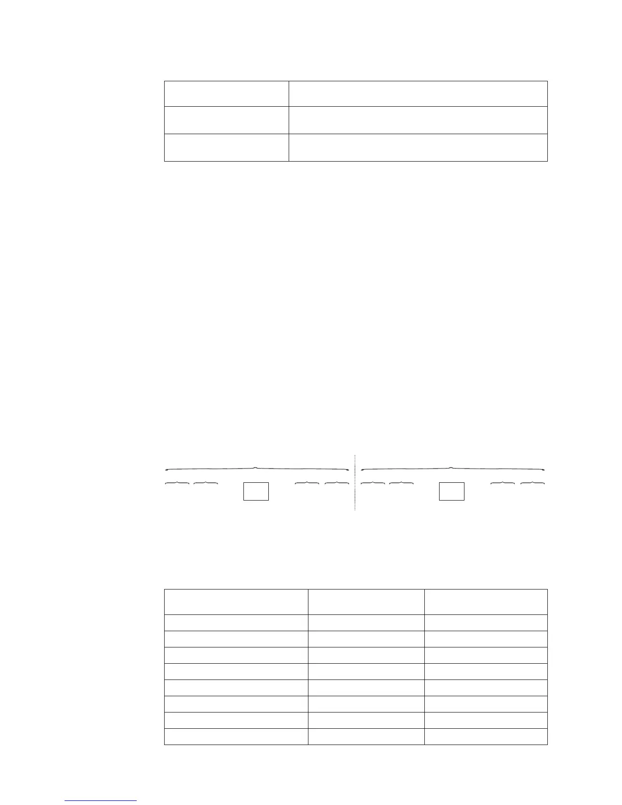
The following diagram lists the DIMM connectors on each memory channel.
The following table shows the installation sequence for memory mirrored channel
mode:
Table 16. Memory mirrored channel mode DIMM population sequence
Number of DIMMs
Number of installed
microprocessor DIMM connector
First pair of DIMMs 1 1, 4
Second pair of DIMMs 1 9, 12
Third pair of DIMMs 1 2, 5
Fourth pair of DIMMs 1 8, 11
Fifth pair of DIMMs 1 3, 6
Sixth pair of DIMMs 1 7, 10
Seventh pair of DIMMs 2 13, 16
Eighth pair of DIMMs 2 21, 24
DIMM 3
DIMM 9
DIMM 6
DIMM 12
DIMM 2
DIMM 8
DIMM 5
DIMM 11
DIMM 1
DIMM 7
DIMM 4
DIMM 10
CH1Ch2 CH0Ch3
Microprocessor 1
CPU1
DIMM 15
DIMM 21
DIMM 18
DIMM 24
DIMM 14
DIMM 20
DIMM 17
DIMM 23
DIMM 13
DIMM 19
DIMM 16
DIMM 22
CH1Ch2 CH0Ch3
Microprocessor 2
CPU2
Figure 1. Connectors on each memory channel
254 IBM System x3650 M4 Type 7915: Problem Determination and Service Guide

 Loading...


