v Remind button: This button places the system-error LED/check log LED on the
front information panel into Remind mode. In Remind mode, the system-error
LED flashes every 2 seconds until the problem is corrected, the system is
restarted, or a new problem occurs.
By placing the system-error LED indicator in Remind mode, you acknowledge
that you are aware of the last failure but will not take immediate action to correct
the problem. The remind function is controlled by the IMM2.
v Reset button: Press this button to reset the server and run the power-on
self-test (POST). You might have to use a pen or the end of a straightened paper
clip to press the button. The Reset button is in the lower right-hand corner of the
light path diagnostics panel.
For additional information about the light path diagnostics panel LEDs, see “Light
path diagnostics” on page 124.
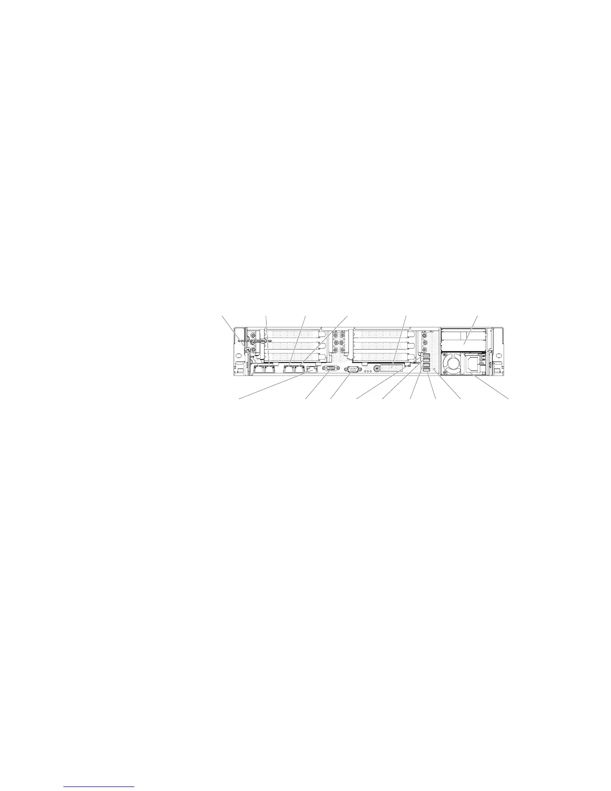
Rear view
The following illustration shows the connectors on the rear of the server.
Video Serial
Power supply 1
Power supply 2
Ethernet1
(shared system
management ethernet)
Ethernet2 Ethernet3 Ethernet4
System-management
(ethernet)(dedicated)
10G ethernet
(with optional
10G ethernet card)
USB5USB3 USB4 USB6 NMI
button
Ethernet connectors: Use either of these connectors to connect the server to a
network. When you enable shared Ethernet for IMM2 in the Setup utility, you can
access the IMM2 using either the Ethernet 1 or the system-management Ethernet
(default) connector. See “Using the Setup utility” on page 301 for more information.
Power-cord connector: Connect the power cord to this connector.
USB connectors: Connect a USB device, such as USB mouse, keyboard, or other
USB device, to any of these connectors.
Serial connector: Connect a 9-pin serial device to this connector. The serial port is
shared with the integrated management module II (IMM2). The IMM2 can take
control of the shared serial port to redirect serial traffic, using Serial over LAN
(SOL).
Video connector: Connect a monitor to this connector. The video connectors on
the front and rear of the server can be used simultaneously.
Note: The maximum video resolution is 1600 x 1200 at 75 Hz.
Systems-management Ethernet connector: Use this connector to connect the
server to a network for full systems-management information control. This connector
is used only by the integrated baseboard management controller (iBMC). A
dedicated management network provides additional security by physically
separating the management network traffic from the production network. You can
12 IBM System x3650 M4 Type 7915: Problem Determination and Service Guide

 Loading...


