resources. To view the total amount of installed memory and the amount of
configured memory, run the Setup utility. For additional information, see
“Configuring the server” on page 298.
v A minimum of one DIMM must be installed for each microprocessor. For
example, you must install a minimum of two DIMMs if the server has two
microprocessors installed. However, to improve system performance, install a
minimum of four DIMMs for each microprocessor.
v DIMMs in the server must be the same type (RDIMM, UDIMM, HCDIMM or
LRDIMM) to ensure that the server will operate correctly.
v When you install one quad-rank DIMM in a channel, install it in the DIMM
connector furthest away from the microprocessor.
v For UDIMMs, DIMM connectors 3, 6, 7, and 10 for microprocessor 1 and DIMM
connectors 15, 18, 19, and 22 for microprocessor 2 are not used.
Notes:
1. You can install DIMMs for microprocessor 2 as soon as you install
microprocessor 2; you do not have to wait until all of the DIMM slots for
microprocessor 1 are filled.
2. DIMM slots 13-24 are reserved for microprocessor 2; thus, DIMM slots 13-24
are enabled when microprocessor 2 is installed.
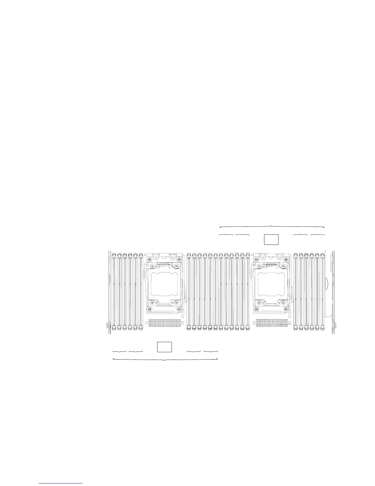
The following illustration shows the location of the DIMM connectors on the system
board.
DIMM 3
DIMM 9
DIMM 6
DIMM 12
DIMM 2
DIMM 8
DIMM 5
DIMM 11
DIMM 1
DIMM 7
DIMM 4
DIMM 10
CH1Ch2 CH0Ch3
Microprocessor 1
CPU1
DIMM 15
DIMM 21
DIMM 18
DIMM 24
DIMM 14
DIMM 20
DIMM 17
DIMM 23
DIMM 13
DIMM 19
DIMM 16
DIMM 22
CH1Ch2 CH0Ch3
Microprocessor 2
CPU2
DIMM installation sequence
Depending on the server model, the server may come with a minimum of one 2 GB
or 4 GB DIMM installed in slot 1. When you install additional DIMMs, install them in
the order shown in the following table to optimize system performance. In
non-mirroring mode, all three channels on the memory interface for each
microprocessor can be populated in any order and have no matching requirements.
Chapter 5. Removing and replacing server components 253

 Loading...


