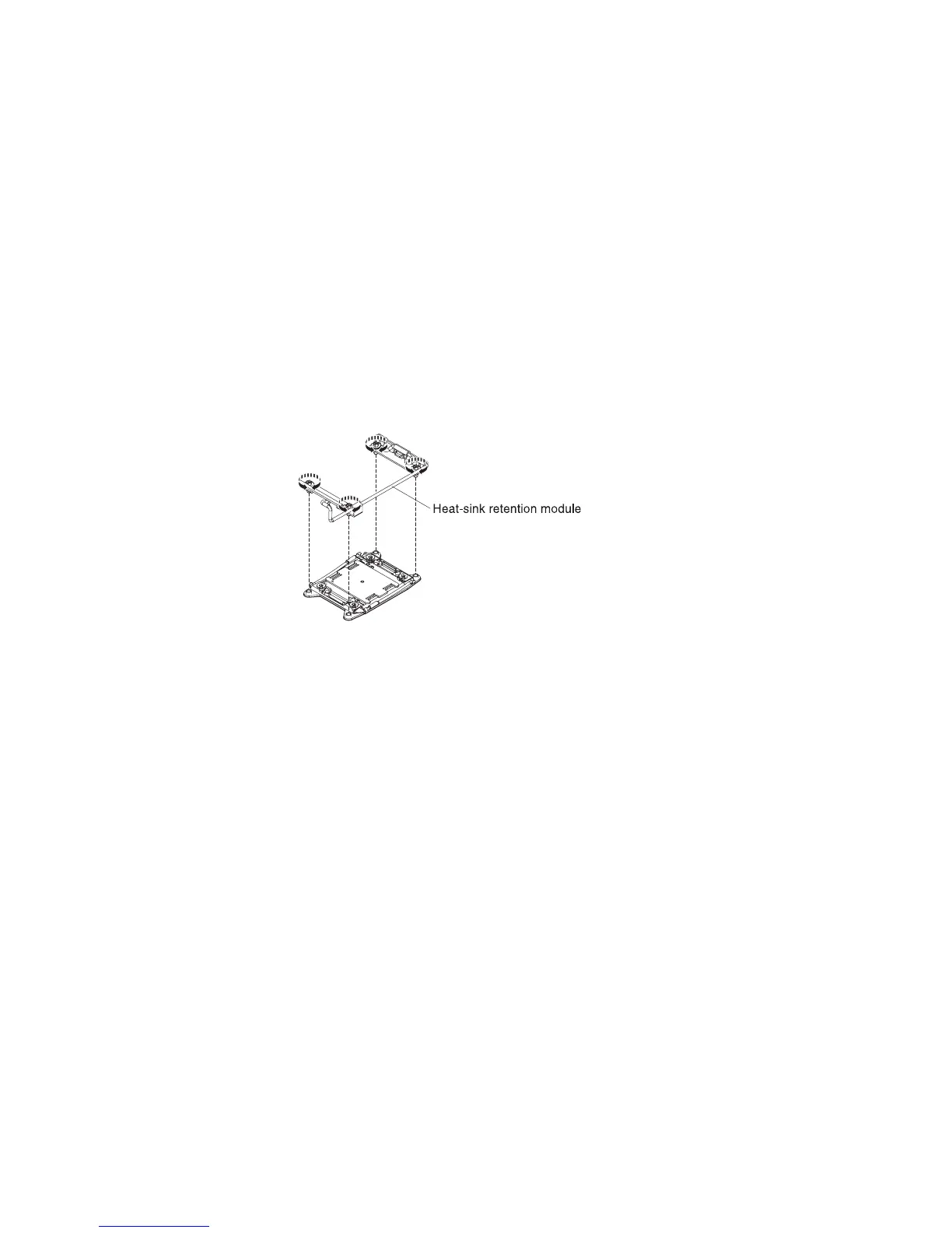
Removing a heat-sink retention module
To remove a heat-sink retention module, complete the following steps:
1. Read the safety information that begins on page vii and “Installation guidelines”
on page 191.
2. Turn off the server, and disconnect all power cords and external cables.
3. Remove the cover (see “Removing the cover” on page 205).
Attention: In the following step, keep each heat sink paired with its
microprocessor for reinstallation.
4. Remove the applicable air baffle; then, remove the heat sink and
microprocessor. See “Removing a microprocessor and heat sink” on page 279
for instructions; then, continue with step 5.
Attention: When you remove a microprocessor and heat sink, be sure to
keep each heat sink with its microprocessor for reinstallation.
5. Use a screwdriver and remove the four screws that secure the retention module
to the system board; then, lift the retention module from the system board.
6. If you are instructed to return the heat-sink retention module, follow all
packaging instructions, and use any packaging materials for shipping that are
supplied to you.
Installing a heat-sink retention module
To install a heat-sink retention module, complete the following steps:
1. Read the safety information that begins on page vii and “Installation guidelines”
on page 191.
2. Turn off the server and any attached devices.
3. Turn off the peripheral devices and disconnect all power cords; then, remove
the cover (see “Removing the cover” on page 205).
4. Depending on which heat-sink retention module you are removing, remove the
following components, if necessary:
v Microprocessor 1: PCI riser-card assembly 1 and DIMM air baffle (see
“Removing a PCI riser-card assembly” on page 218 and “Removing the air
baffle” on page 206)
v Microprocessor 2: PCI riser-card assembly 2 (see “Removing a PCI
riser-card assembly” on page 218).
5. Align the retention module with the holes on the system board.
6. Use a screwdriver to reinstall the four screws.
Chapter 5. Removing and replacing server components 289

 Loading...


