Table 42. Rear panel descriptions (continued)
Number Item Comments
5 USB port Base Module only
6 Ethernet port B Base Module only (secondary port for service
usage)
7 Ethernet port A Base Module only
8 Module alignment mechanism
9 Lower Expansion Module connection port
10 Unit Identier LED, Blue
11 Controller Error LED, Yellow
12 Controller Health Status LED, Green
13 Product Serial Number, Tag location
3. On the back of each tape drive. See Figure 65 on page 97 and Table 43 on page 97.
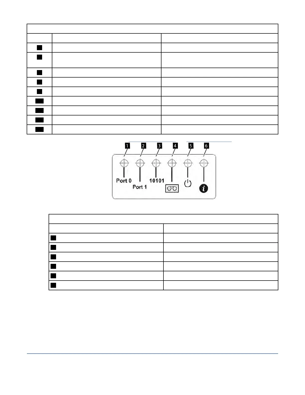
Figure 65. Drive sled indicators
Table 43. Drive sled indicators
Number Description
1 Port 0 activity
2 Port 1 activity
3 Library communication
4 Cartridge present
5 Power
6 Beacon /UID
Note: The Library Front Panel UID and the base module LCC UID are linked. They turn on and off together.
The F
ront Panel UID helps a user nd the library in the front of a rack. The UID on the controllers and
Drives in the rear of the library help identify a component within a library. When a component experiences
an error, a user with superuser, service, or administer privileges can turn on the UID for that component.
The UID helps to physically locate the components in a complex assortment of IT equipment. UID menus
are in the actions button at the top of the library dashboard. See the help pages for instructions on turning
on and off the Unit Identier LEDs.
Identifying a failed power supply
When a power supply is in a fault condition, error messages identify which module has the faulty supply.
IBM Condential
Chapter 5. Troubleshooting97