Removing the controller card
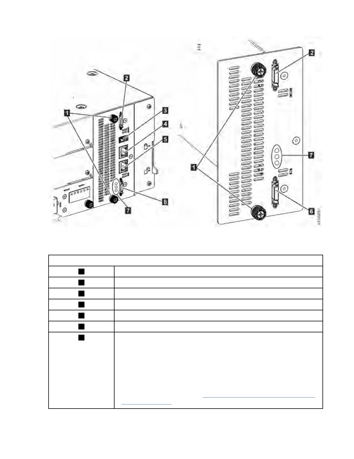
Figure 78. Controller card components
Note: The base controller card is on the left, and the expansion controller card is on the right.
Table 54. Controller card components
1 Blue captive thumbscrews
2 Upper Expansion Module connection port
3 USB Port
4 Ethernet Port A
5 Ethernet Port B
6 Lower Expansion Module connection port
7 Controller card LEDs, top to bottom
• Green Controller Health Status. The flashing LED indicates that the controller
is in good health status and properly working.
• Yellow Controller Error. This LED turns on if the controller has a hardware
issue. In this case, the green LED stops flashing.
• Blue Unit Identier. This LED is a beacon that can be turned on or off
through the Management GUI. The LED gives the user an indication that the
controller needs attention. See “Locating faulty Components and Resolving
Issues” on page 94.
1. Unplug the AC power cables from the module that contains the failed controller card.
IBM Condential
164IBM TS4300 Tape Library Machine Type 3555: User's Guide