Section 2 - Product Information
PRODUCT INFO
10 Installation and Servicing
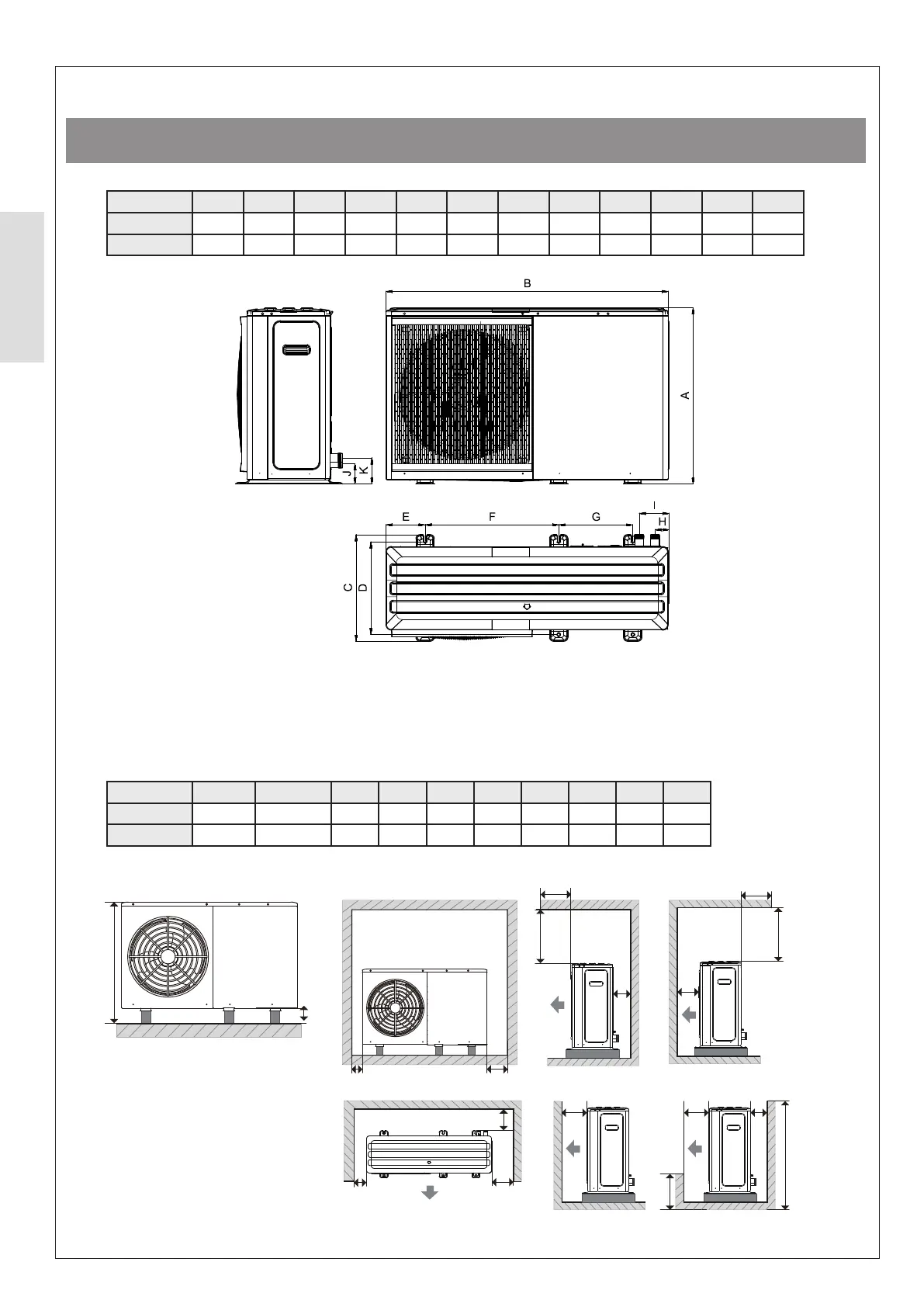
2.2.1 Dimensions and Clearances
ᘐ CAUTION: The product is not to be obstructed by any surrounding objects or surfaces as this can limit access
and adversely aect performance. The minimum clearances that are shown in Figure 2 should be always maintained.
Figure 2. Heat Pump - Dimensions
Figure 3. Heat Pump - Clearances
Table 2 Dimensions and clearances
Table 3 Heat Pump Air Flow minimum dimensions
ⓘ IMPORTANT: Dimensions shown below are the minimum required to satisfy the Heat Pump air ow. The
requirements of the Protective Safety Zone - 3.3.6 on page 27 must also be complied with. Consideration must be
given to individual installation, service and maintenance access requirements.
Model Units A B C D E F G H I
4.5 - 8 kW mm Height + B
10 - 14 kW mm Height + B
being blocked by the build-up of snow. This dimension must not exceed 1000 mm.
A
B
C
C
D
E
D
E
F
F
F
G
X(X<A)
Wall height unrestricted
I
H
H
C
Model Units A B C D E F G H I J K
4.5 - 6 kW mm 717 1299 426 375 121 644 379 71 161 91 91
8 - 14 kW mm 865 1385 523 456 192 656 363 68 145 100 129