Section 5 - Commissioning
COMMISSIONING
55
Installation and Maintenance
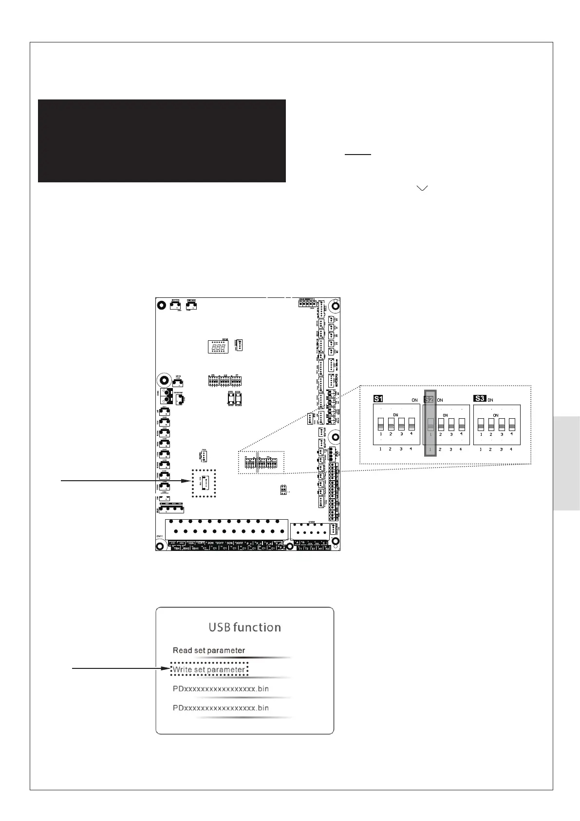
Figure 55. Outdoor PCB
Figure 56. Control Box display
5.5.3 HP290 System Parameter Update using
USB
ᘐ WARNING: All electrical work is to be undertaken
by a competent electrician. The electrical supply is to be
switched o with appropriate safety measures in place to
prevent accidental activation. The electrical installation
must be done on the Heat Pump rst and connection to
the supply must be the last connection made to reduce
risk of electric shock.
Commission the Heat Pump USB as follows:
1. Make Make sure that the appliance power is set to OFF.
2. On the Outdoor PCB (Figure 55) insert the USB stick
(provided) into the slot marked CN4 USB.
CN4 USB slot
Option illuminated
Dip-switch S2 (switch 1)
3. Power up the indoor unit and then power up the outdoor
unit. Wait until the Control display shows the USB
FUNCTION window (Figure 56).
Note 1. This may take up to 30 seconds.
Note 2. Do not touch the display during this time. If the
display is touched, the system will return to the Home
screen and you will have to do Step 1 again.
4. On the Control Box, press to scroll through the options.
When WRITE SET PARAMETER is illuminated on the
display (Figure 56), press O (to select the option).
5. When a pop-up window shows SUCCESS, set the power
on the indoor and outdoor units to OFF.
6. Remove the USB stick.
7. Set the power on the indoor and outdoor units to ON.