Section 4 - Installation
INSTALLATION
45
Installation and Maintenance
Note: Section 4.3.1 to 4.3.3 is only applicable if using a non
pre-plumbed cylinder, as the control box will be packaged and
supplied separately.
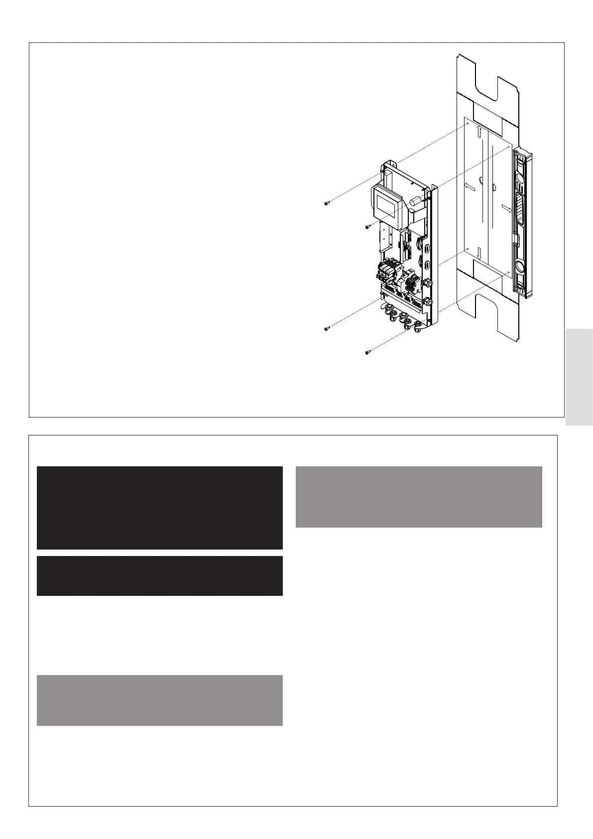
Hang the wall mounting template supplied on the wall, using a
spirit level.
indicated in Figure 45 onto the wall mounting template.
It is the responsibility of the installer to determine appropriate
sturdy.
4.3.3 Mounting
Figure 45. Front Panel Mounting
4.3.4 Electrical Installation
ᘐ WARNING: All electrical work is to be done by
a competent electrician. The electrical supply is to
be switched o with appropriate safety measures in
place to prevent accidental activation. The electrical
installation must be done on the heat pump rst and
connection to the supply must be the last connection
made to reduce risk of electric shock.
ᘐ WARNING: This product must be earthed, and
it must not be possible to disconnect the protective
conductor through any isolator switches.
Electrical installations must comply with the requirements
and guidance of the IET Wiring Regulations BS 7671, and
these guidelines are to be used to determine the cross-
sectional area of the electrical cable.
The electrical installation must be installed in accordance
Table 9.
ᘐ CAUTION: Incorrect installation of the electrical
supply can lead to the destruction of the electrical
components in the heat pump and any other unit that it
is connected to.
Cables that are connecting to the heat pump are to be routed
through the cable glands and through to the circuit board as
shown in Figure 39. Power cables and communication/signal
cables must be separated by a minimum distance of 100mm
and routed through separate glands to prevent electrical
interference.
ᘐ CAUTION: When routing cables, care should be
taken to make sure that water is not able to run down
the cables and enter the product by making sure that
the cable is routed downwards after leaving the product
and that the cable glands are tightly tted.
Connections are to be made using the plastic terminal
connectors supplied within the control box. When making
connections to the electrical terminals make sure that there
is no exposed copper wire.
Multi core cables should be stripped back by at least 60mm
to allow for easy connection and to reduce strain on the
terminals. Once all connections have been made, the cables
are to be secured using the cable securing clamps at the
base of the control board, to prevent stress on the terminals.