Section 9 - Fault Finding
107
Installation and Maintenance
FAULT FINDING
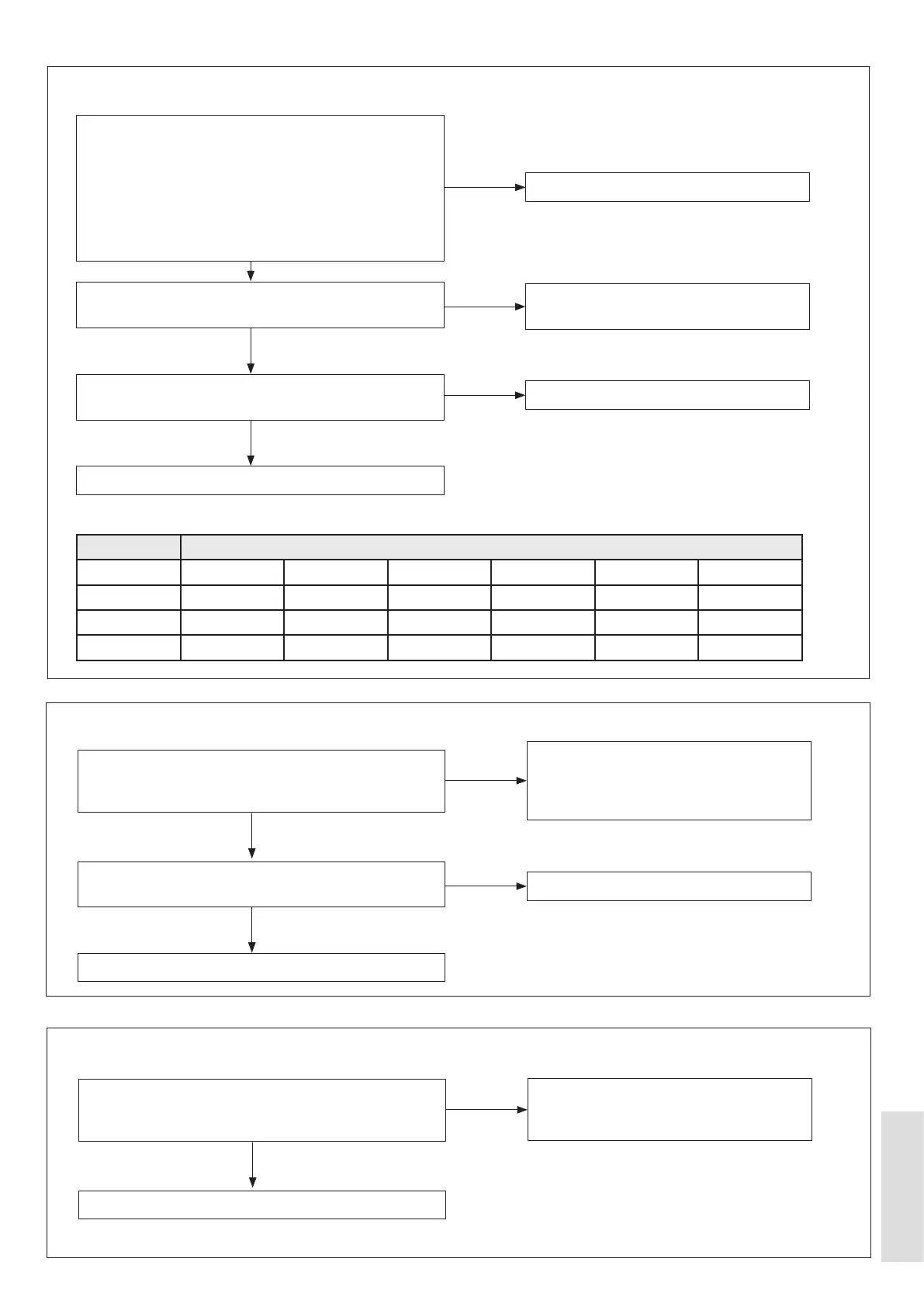
9.1.29 Low Pressure Sensor Error
9.1.30 High Pressure Sensor and Low Pressure Sensor Wiring-Cross-Connection
Is the cable from the Outdoor PCB to the Low Pressure
Sensor undamaged and dry?
Refer to Figure 67 on page 116.
Are the wiring assemblies to the High Pressure sensor
and Low Pressure sensor installed correctly?
Refer to Figure 67 on page 116.
Disconnect the Low Pressure Sensor. Is the displayed
voltage between 0.5 V DC and 4.5 V DC?
Replace the Outdoor PCB.
Replace the Outdoor PCB.
The wiring assembly must be undamaged,
the connections must be dry, and the
wiring assembly must be correctly
connected to the Low Pressure Sensor.
Refer to the applicable wiring diagrams.
Make sure that the wiring assemblies are
installed correctly.
Replace Low Pressure Sensor.
NO
NO
NO
YES
YES
YES
Remove the Discharge Thermistor (Tp) from the
the thermistor reading is correct. Refer to the values
shown below:
Are the Outdoor Unit Flow thermistor and the Return
thermistor installed correctly?
Is the P1 comp. pressure correct? Refer to Table 23 -
Discharge pressure (P1 for heating / DHW mode).
Replace the Outdoor PCB.
Replace Discharge Thermistor.
Install the Flow Thermistor and the Return
Thermistor.
Repressurise the refrigerant.
NO
NO
NO
YES
YES
YES
Unit Value
25 30 35 40 45 50
P1 (kPa)
1000 ±100 1150 ±100 1300 ±100 1450 ±100 1600 ±100 1800 ±100
55 60 65 70 75
P1 (kPa)
2000 ±150 2200 ±150 2450 ±150 2700 ±150 3000 ±150
Note: P1 is absolute pressure.
Table 23 Discharge pressure (P1) for heating/DHW mode
9.1.28 Compressor Discharge Temperature High Error