Section 4 - Installation
INSTALLATION
42 Installation and Maintenance
4.2.4 Pressure and Temperature/Expansion Relief
Valve Pipework
The relief valve should be installed to discharge in accordance
with G3 of the Approved Document of the Building Regulations and
should be piped to where it is visible, but will not cause danger to
persons or damage to materials.
The following information is taken from Approved Document G3 of
the Building Regulations and is provided to assist with the design
and installation of the discharge pipework. However, the information
is not exhaustive and reference should always be made to Approved
regarding any arrangements rests with Building Control and it is
recommended that their advice is sought if you have any concerns
regarding this aspect of the installation.
The two safety valves will only discharge water under fault
conditions. When operating normally water will not be discharged.
The tundish should be vertical, located in the same space as
possible and within 600mm of the safety device e.g. the temperature
relief valve.
The discharge pipe (D2) from the tundish should terminate in a
safe place where there is no risk to persons in the vicinity of the
discharge, or other material that has been demonstrated to be
capable of safely withstanding temperatures of the water discharged
and is clearly and permanently marked to identify the product and
performance standard and:
A. Be at least one pipe size larger than the nominal outlet size of
the safety device unless its total equivalent hydraulic resistance
exceeds that of a straight pipe 9m long i.e. discharge pipes
between 9m and 18m equivalent resistance length should be at
least two sizes larger than the nominal outlet size of the safety
device, between 18 and 27m at least 3 sizes larger, and so
resistance. Refer to the Table 14 and the worked example.
An alternative approach for sizing discharge pipes would be to
testing and maintenance of services supplying water for
domestic use within buildings and their curtilages.
B. Have a vertical section of pipe at least 300mm long, below the
tundish before any elbows or bends in the pipe work.
C. Be installed with a continuous fall.
D. It is preferable for the discharge to be visible at both the tundish
other of these locations. Examples of acceptable discharge
arrangements are:
1.
trapped gulley.
2. Downward discharges at a low level; i.e. up to 100
mm above external surfaces such as car parks, hard
standings, grassed areas etc are acceptable providing that
where children play or otherwise come into contact with
discharges, a wire cage or similar guard is positioned to
prevent contact when maintaining visibility.
3.
Discharges at a high level; e.g. into metal hopper and metal
down pipe with the end of the discharge pipe clearly visible
(tundish visible or not) or onto a roof capable of withstanding
high temperature discharges of water and 3 m from any
plastic guttering systems that would collect such discharges.
4. Where a single common discharge pipe serves more than
one system, it should be at least one pipe size larger than
the largest individual discharge pipe (D2) to be connected.
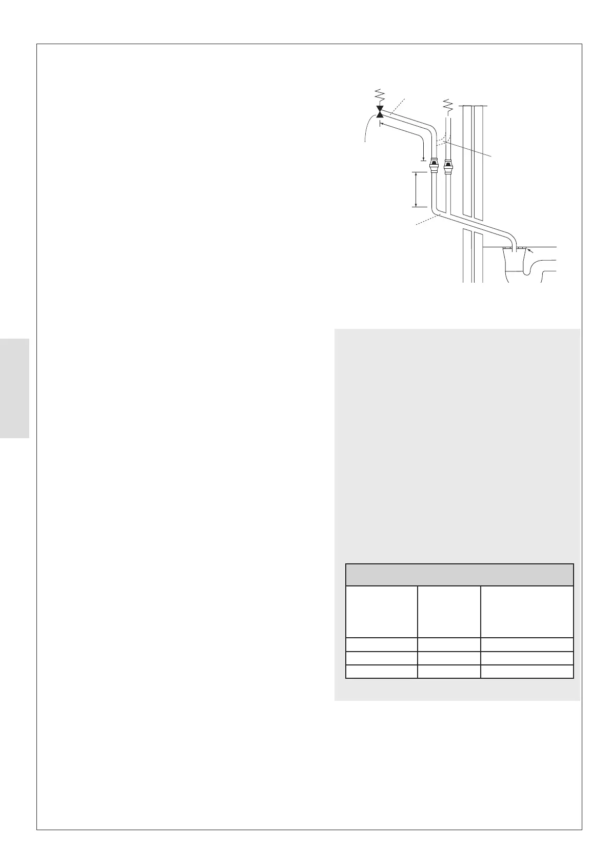
15 mm
discharge
pipe
Expansion
relief valve
Typical Discharge Pipe Arrangement
Dotted line showing
alternative route with
single tundish being used
600 mm max.
P & T
Relief
Valve
300 mm
min.
22 mm metal pipe with continuous
fall up to 9m equivalent length (D2).
The discharge will consist of scalding
water and steam. Asphalt, roofing felt
and non-metallic rainwater goods may
be damaged by such discharges.
It is not acceptable to discharge straight
into a soil pipe.
Discharge below
fixed grating
Fixed Grating
Trapped gully
Worked Example
The example below is for G1/2 temperature relief valve with
a discharge pipe (D2) having 4 elbows and length of 7m from
the tundish to the point of discharge.
From Table 14:
Maximum resistance allowed for a straight length of 22mm
copper discharge pipe (D2) from a G1/2 temperature relief
valve is: 9m subtract the resistance for 4 x 22mm elbows at
0.8m each = 3.2m.
Therefore the maximum permitted length equates to: 5.8m.
5.8m is less than the actual length of 7m therefore calculate
the next largest size.
Maximum resistance allowed for a straight length of 28mm
pipe (D2) from a G1/2 temperature relief valve equates to:
14m.
As the actual length is 7m, a 28mm (D2) copper pipe will be
satisfactory.
Sizing of copper discharge pipe ‘D2’ for a temperature relief
valve with a G1/2 outlet size (as supplied)
Size of discharge
pipework
Maximum length
of straight pipe
(no bends or
elbows)
from the maximum length
for each bend or elbow in
the discharge pipe
22mm Up to 9m 0.8m
28mm Up to 18m 1m
35mm Up to 27m 1.4m
Figure 42. Typical Discharge Pipe Arrangement
Table 14 Sizing of Copper Discharge Pipe
5. If unvented hot water storage systems are installed
where discharges form safety devices may not be
or disabled people, consideration should be given
to the installation of an electronically operated
device to warn when discharge takes place.