Section 4 - Installation
INSTALLATION
43
Installation and Maintenance
Safety
selected for their suitability for the temperatures and pressures
involved. They must not be changed, removed or by-passed
and it is essential that only genuine replacement parts
supplied or approved by Ideal heating Ltd are used. All parts
are available to approved installers from Ideal heating spares
department (Telephone 01482 498663).
Combination Inlet Group
Combines elements 1, 2 and 3 below.
1. Pressure Reducing Valve - The cold water supply to any
mixer taps/showers must be taken from the cold water
tapping of this valve to ensure balanced hot and cold
pressures. This valve is factory set to ensure the correct
operating pressure for the StainlessLite Plus.
2. Non Return Valve - This is integral with the pressure
3. Cold Water Expansion Relief Valve - This safety device
is preset at the factory and will relieve excess cold water
pressure resulting from a fault condition.
Line Strainer
This is integral within the combination inlet group to reduce the
likelihood of contaminants fouling the valve seat. Following
installation; Isolate the cold supply to the cylinder. Remove the
side of the valve and remove the debris.
Tundish
This is to allow the discharge from any Relief Valve to be
page 36 for discharge pipework details.
Expansion Vessels Installation
To prevent water stagnation and particulate accumulation
accommodating thermal expansion or a pressure surge is:-
1. bottom fed and upright; and
2.
- rises continuously; and
- is kept to a minimum;
There must be no valve on the pipe work between the
expansion vessels and the unvented cylinder which could
prevent the expansion of the water contained in the unvented
cylinder reaching the expansion vessels.
Temperature/Pressure Relief Valve
This safety device is also pre-set at the factory and relieves
before the temperature reaches 100°C. It is also a Pressure
Relief Valve, and is pre-set to 6 bar.
4.2.5 Immersion Heater Wiring
ᘐ WARNING:
Danger of electrocution: before making any
adjustments to the thermostat isolate the immersion heater
from the mains electricity supply at the fuse spur unit.
The immersion heater supplied with Heat pump products is
set to max; so will operate in the range 68 °C ± 3 °C.
The immersion heater thermostat should be left on set
position 5; If the immersion heater thermostat is set too low
the Legionella Cycle will fail to complete correctly.
5
4
3
2
1
1
1
2
A
A
B
R
2
Safety
B
EN
EC
15
T
1
1
5
1
6
A
2
5
0
V
~
TSR
Type:
COTHERM
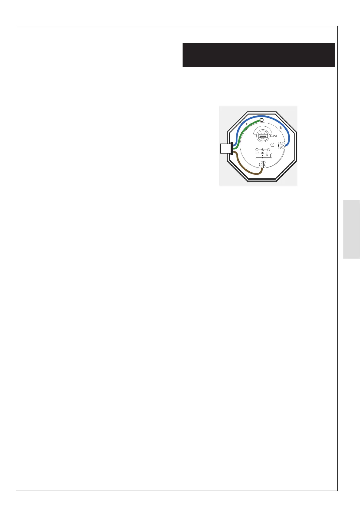
Figure 43. Immersion Heater Wiring
Immersion Heater
Check that the mains supply conforms to this, and all external
wiring conforms to the most recent revision of the IEE wiring
regulations. An Incoloy element is used on this product for
standard domestic use and water conditions.
determine if the O-ring has sealed and tighten carefully using
the appropriate tool. To prevent damage to the O ring do not
use excessive force to tighten the immersion heater.
The immersion heater is supplied with a thermostat which has
been tested for operation in the cylinder and complies with
the European directives for Electromagnetic compatibility and
The immersion thermostat has two terminals A and B. The
Live (brown) wire should be connected to terminal A and
the Neutral (blue) wire should be connected to terminal B. It
has been our experience that Crimp terminals make better
connections. The immersion heater must be fully earthed
(earth post) and connected via a double pole isolator switch
having a contact separation at least 3mm, see diagram above.
The immersion heater thermostats incorporate a manual
reset safety/overheat cut out thermostat. Should this operate,
investigate the cause for the operation cut out before pressing
the red reset button labelled safety. If there is no apparent
fault adjust the control setting down slightly to prevent
nuisance tripping.
If another heat source is used to heat the cylinder and this is
allowed to raise the water temperature excessively then the
overheat thermostat will trip. This is likely on solar thermal
products when the solar thermostats are set at high temperatures.
so that the store temperature can be raised above that which
the heat pump provides, to boost the hot water performance
if necessary and to protect against legionella eg. following the
time parameters set on the Heat Pump remote control.
Control/Overheat Dual Thermostats
Care must be taken to ensure that the probes are fully
inserted into the pockets provided.